One Winter break my Dad and I tracked down a retiree a couple hours away who had experience with the old Shizuoka mills and their spindle drives, and he explained that 9/10 times these drives fail they just need new power diodes and SCRs.
A bit of shopping and soldering later, he was right! We had the original Bandit controller running the spindle beautifully. But, we needed the new LinuxCNC controller to run it if I wanted to do anything useful, and that meant reverse engineering the interface between the Bandit and the driver to hijack it.
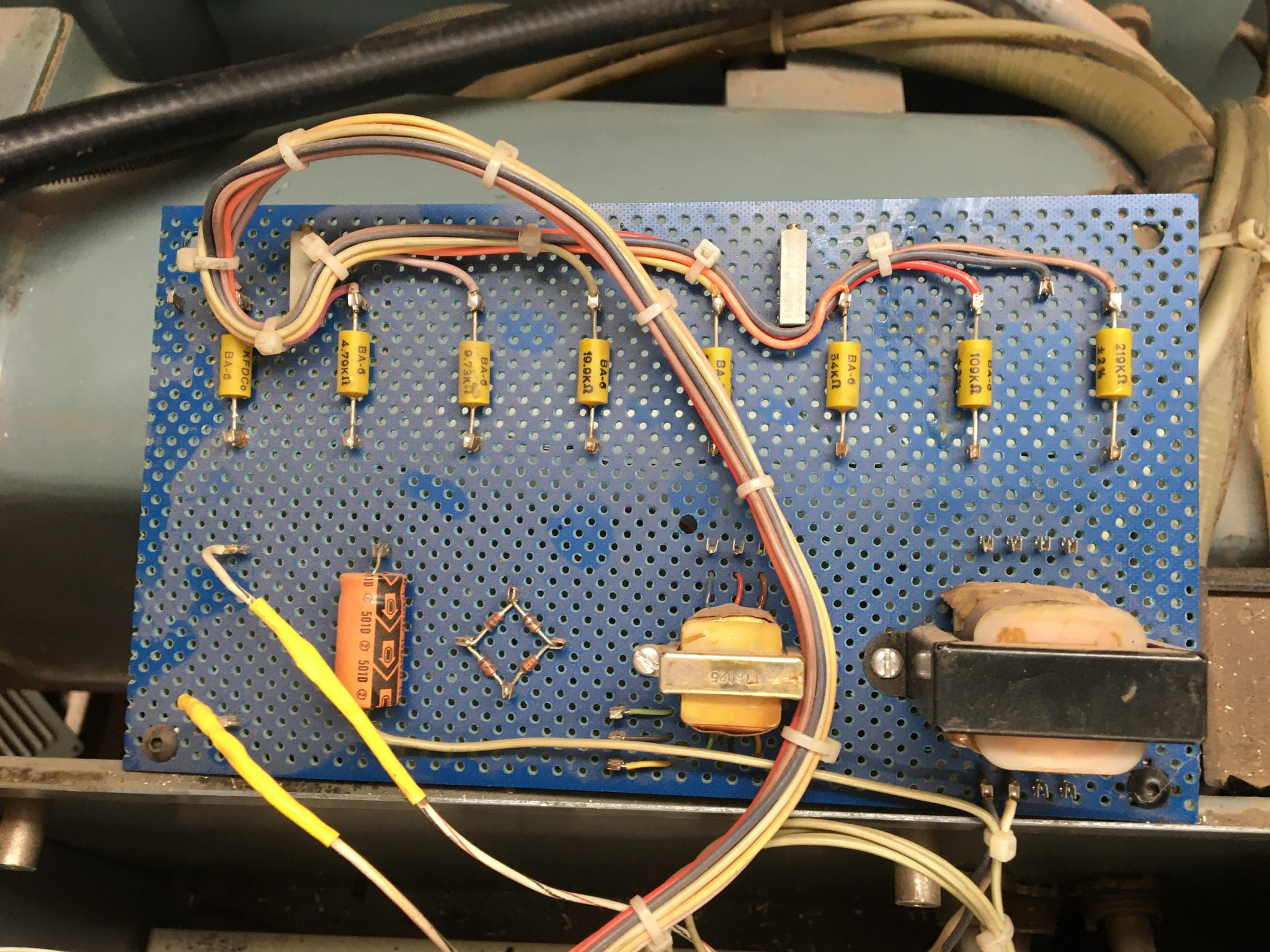
Since the ST-N was originally a manual mill, the factory-built speed input was just a potentiometer ie an adjustable resistance knob on the front panel. When the retrofitting company converted it, they used eight relays and appropriately sized resistors on some breadboard to make a simple digital potentiometer. Weirdly, the resistors were configured for binary coded decimal so they only had 99 steps of spindle speed instead of the 255 they could have made with straight binary. Presumably that was just a quirk of the bandit controller's output.
On-off and direction control on the original mill was a side panel with a direction knob, momentary buttons to start and stop, and toggle functionality provided by these big AC switches which power the stator coils.
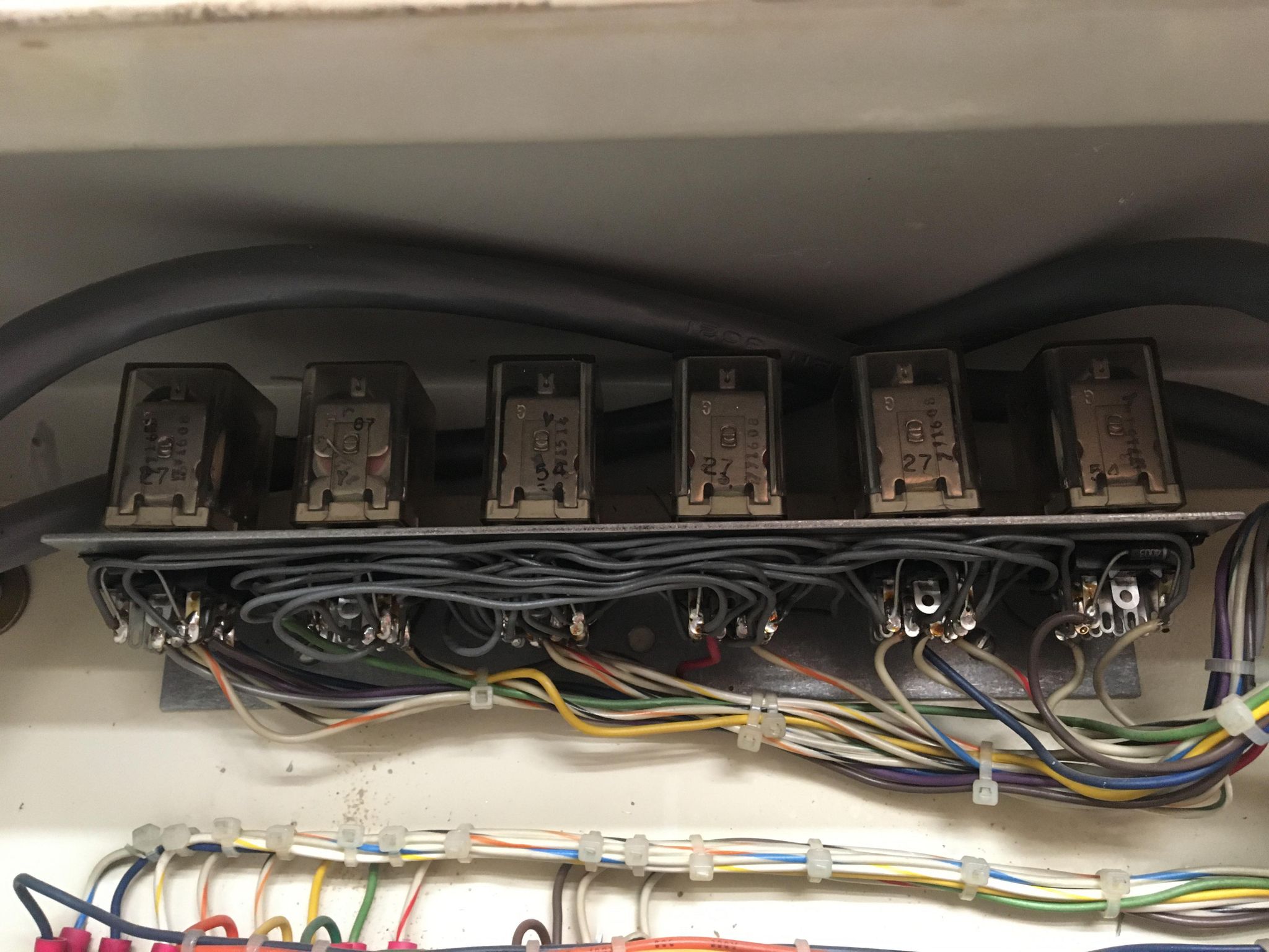
The retrofitters added these six 24V relays in the side cabinet, and a set of momentary buttons on the front panel to control them. They needed to add a couple relays to replace the physical direction knob in the original spindle control panel, but honestly I think most of the rest of this work was pretty sloppy. They duplicated the latching behavior of the original spindle drive, and there's a lot of duplicated logic within the six relays. Working out how these things function was a weird kind of tedious fun. On the other hand, they designed this without circuit design software so maybe let's not judge them too harshly.
I spent a few more hours over the following holiday breaks trying to find a nice way to connect the 0-11V speed input to the LinuxCNC box. This was tricky because I'm not really an electrical engineer and the 0-11V is referenced to my 240V AC neutral input which, as you may remember from earlier, is 120V from ground in my system. I was being very cautious because I didn't want to toast my FPGA or worse my antique stepper drivers by routing 120V through an actual ground someplace.
Returning to the Shiz During Covid
That brings us to covid times. I had motion control of the machine but no spindle control, and worse the spindle was no longer responding correctly to the original bandit controller. I could intermittently start it with a strange sequence of inputs: Command a speed on the bandit, hit spindle enable on the retrofitted front panel, 'rev on' also on the front panel, then hit spindle off on the original side panel. If that didn't work, toggle the spindle off button on the retrofitted front panel and try again. Super weird, right? There must be an interesting failure mode in this antique system there, right? I spent a good month reverse engineering every bit of this system to find the problem, and the final answer was awful. Read on:
The Original Spindle Drive
For background, the spindle motor is a delightfully simple variety called 'shunt-wound DC.' It uses a commutated DC rotor and DC electromagnets for a stator. To change motor direction you just change the polarity applied to the stator. The nice thing about this design is that it's effectively a constant-speed device. Applying a load like, say, the torque required to turn a big endmill in steel, decreases the back-emf on the stator which increases current through both it and the rotor and quickly brings the motor back up to its unloaded speed.
My spindle drive doesn't quite use that trick because the rotor is powered on a separate circuit from the stator (which technically makes it "separately excited DC" not shunt-wound), but it uses a current sense transformer on the rotor to implement the same feedback mechanism as part of the op-amp circuit which also adjusts speed based on the potentiometer input.
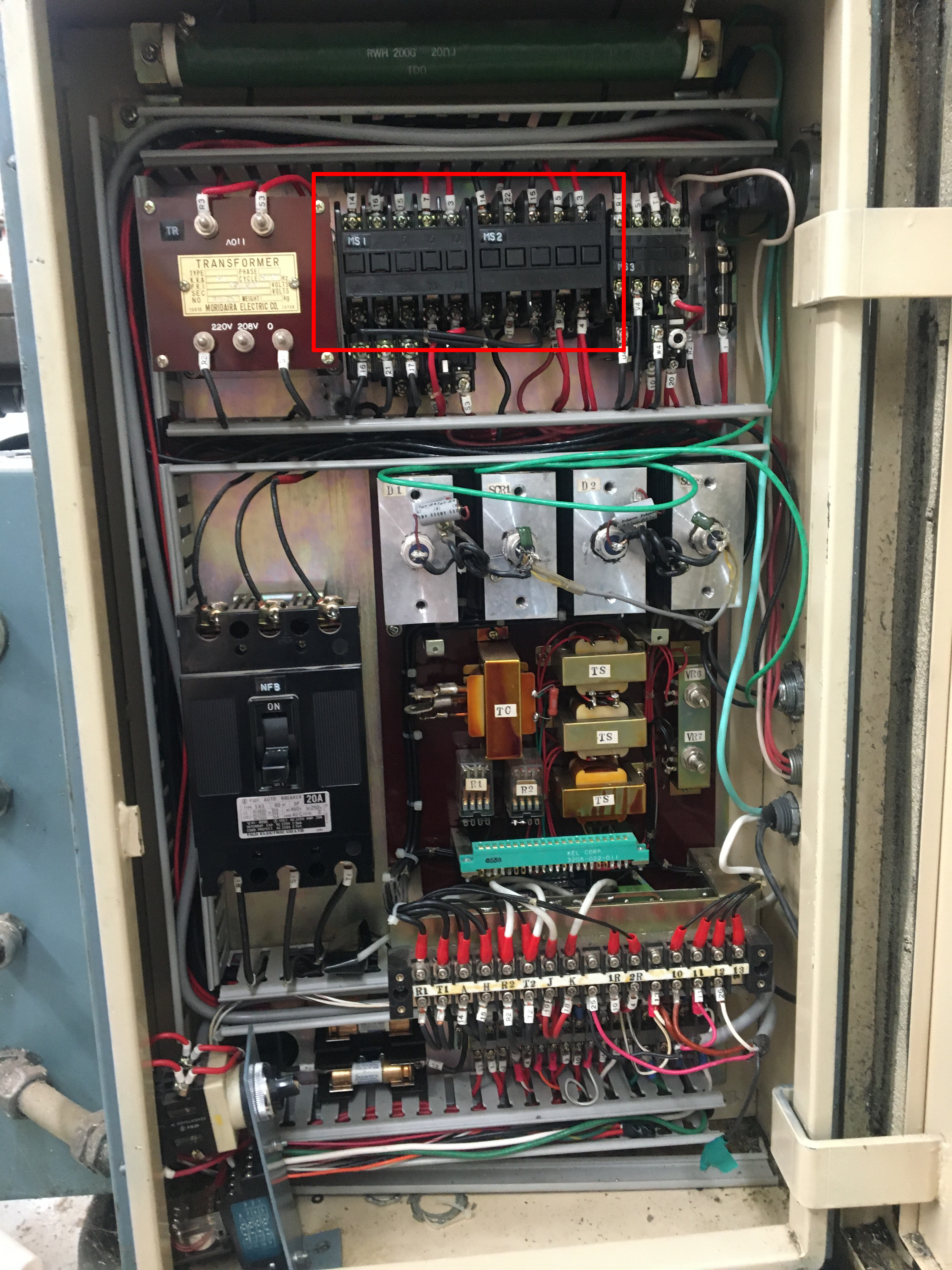
The original circuit was fairly straightforward: The stator drive is a rectifying power supply which applies 240V DC to the coils via the AC mechanical switches. MS1 for one polarity, MS2 for the other. Both switches are spring-loaded and use one of their connections to power themselves so they latch on. The spindle start button powers one or the other based on the position of the direction knob, and the spindle stop button breaks the latch circuit which keeps them powered.
The rotor drive board in the middle is literally a light dimmer circuit, and only has one real input, the 0-11V analog speed signal from the dial on the front. That signal is routed through a small logic relay which disconnects it unless the stator drive is already powered. This is a key safety feature because the stator resistance is 680 ohms so it can sustain continuous 240V across it, but the rotor is 1.2 ohms so it would rapidly burn out if it was powered without a stator field to rotate it and change the applied DC into commutated AC power which is current-limited by induction.
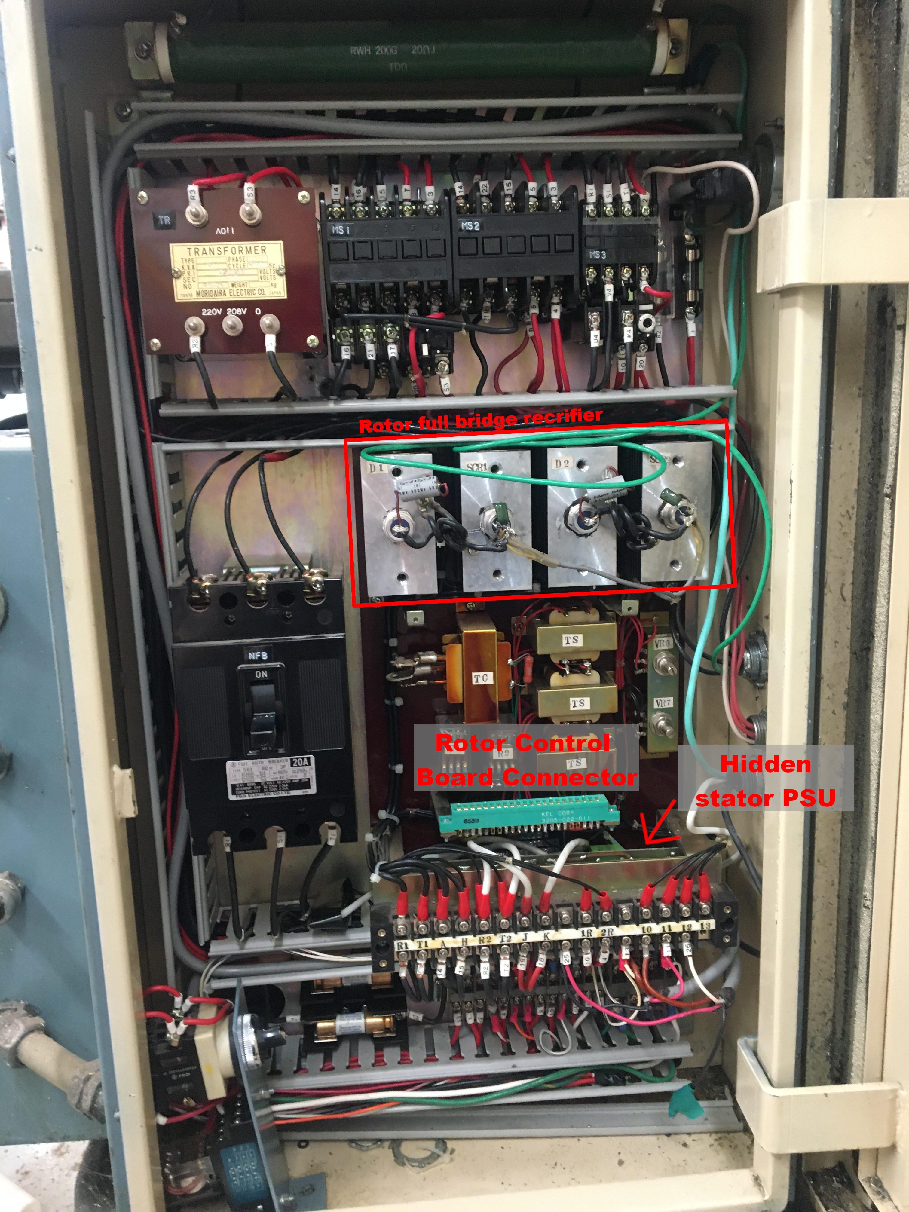
The four large heatsinked components below the AC switches are the power components of the rotor drive. This thing is literally a light dimmer: One phase of my 240V three phase power input is applied to a full bridge rectifier which outputs to the rotor, and one leg of that rectifier is a pair of silicon controlled rectifiers, which are a type of diode that can be turned on with a miniscule current across a gate pin, and will stay on until the voltage from anode to cathode crosses zero. The rotor drive board monitors the current in the stator and pulses the SCR gates earlier or later in the AC waveform to adjust the duty cycle of the rotor and thereby control speed. The SCRs turn off every time the AC wave passes 0V, so you get a chopped sine wave like so as output

The big red transformer makes 110V to run the AC switches, the lube pump, and a few other minor things. The middle components which are normally hidden behind the rotor control board are step-down transformers to make positive and negative logic voltages for the rotor board, one logic transformer to drive the stator board, and a couple needlessly large 10k potentiometers which are used to tune the speed input so the RPM markings on the knob are accurate. I haven't adjusted those.
It's worth pointing out here that I have a separate machine called a rotoconverter just to produce my three-phase power in a residential garage, and aside from the flood coolant pump which I'll never use in my Dad's woodshop, every single component using the three phase power immediately either rectifies it to DC, or transforms it to single phase ~120V AC. If the rotoconverter ever dies or I get tired of listening to it, it's probably $100 in transformers and 6 hours of work to convert everything but that pump to run off the 240V input.
The Debugging Quest
I didn't take great notes over the years with this mill, so I had to guess what past-Nick could have broken and work from there. My first guess was that I had messed up the relays somehow when I fixed my grounding issues or one of them just wasn't firing reliably after all these years, and therefore my 0-11V speed signal simply wasn't reaching the rotor control board. Or perhaps it was reaching it but not quickly enough after the 'turn on' signal and there was some important window there for the motor to start. The way it would intermittently run when I pressed the wrong button supported this theory in my mind - like I was jiggling some relays. Plus, two of the relays are mounted behind the rotor control board, and I can't test the thing with that board removed so debugging their behavior was super tricky.
I didn't get anywhere pursuing that theory with a multimeter and a jumble of notes, so I moved on to trying to understand the connections to the rotor control board some more. It has 22 pins and a lot of them ran off into the transformers and potentiometers mounted behind it, which I didn't yet understand.
That went nowhere as well, so around this time I decided to stop being lazy and draw some circuit diagrams, starting with the power components we replaced for the rotor drive. That made it pretty clear that I was working with a glorified light dimmer, and the function of the rotor control board became more clear. From there I could convince myself I was providing 0-10V signals to the right pins of the rotor control board, and I was quite sure the rotor was the problem because the stator had 240V across it and the rotor had zero.
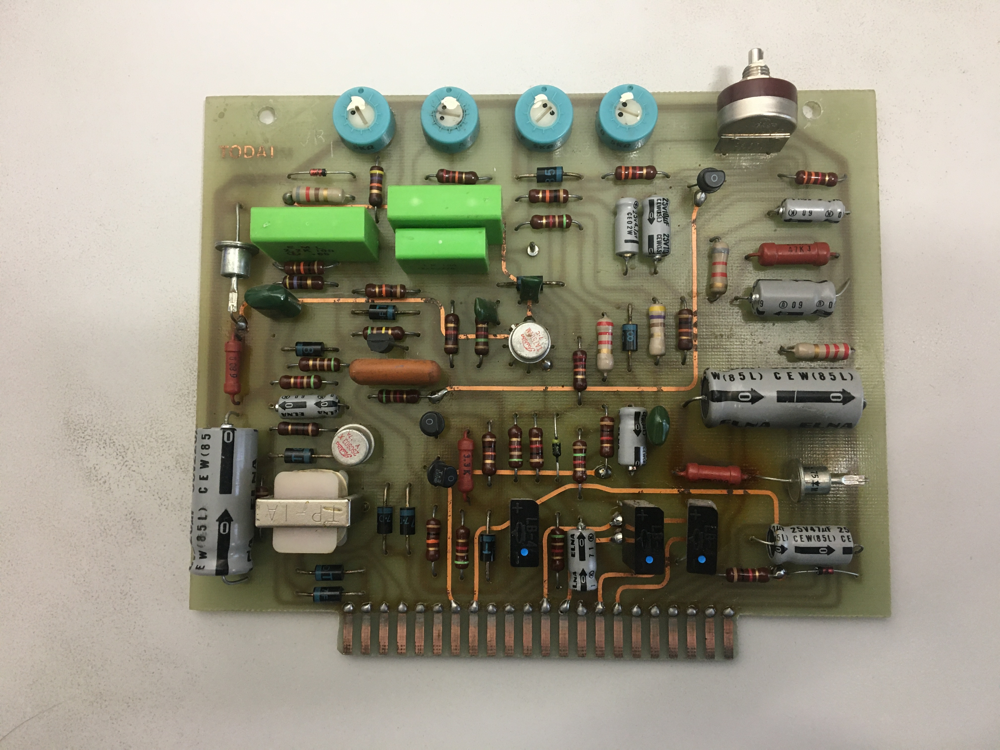
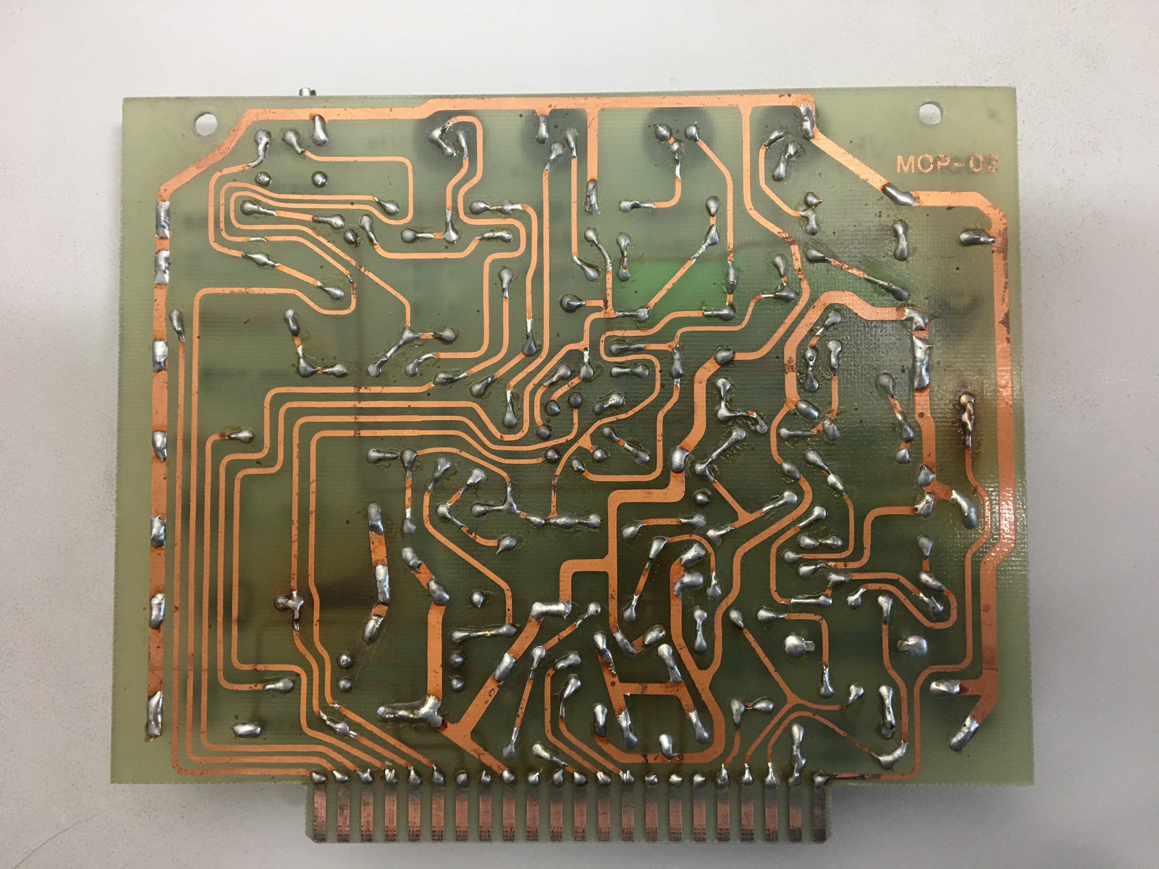
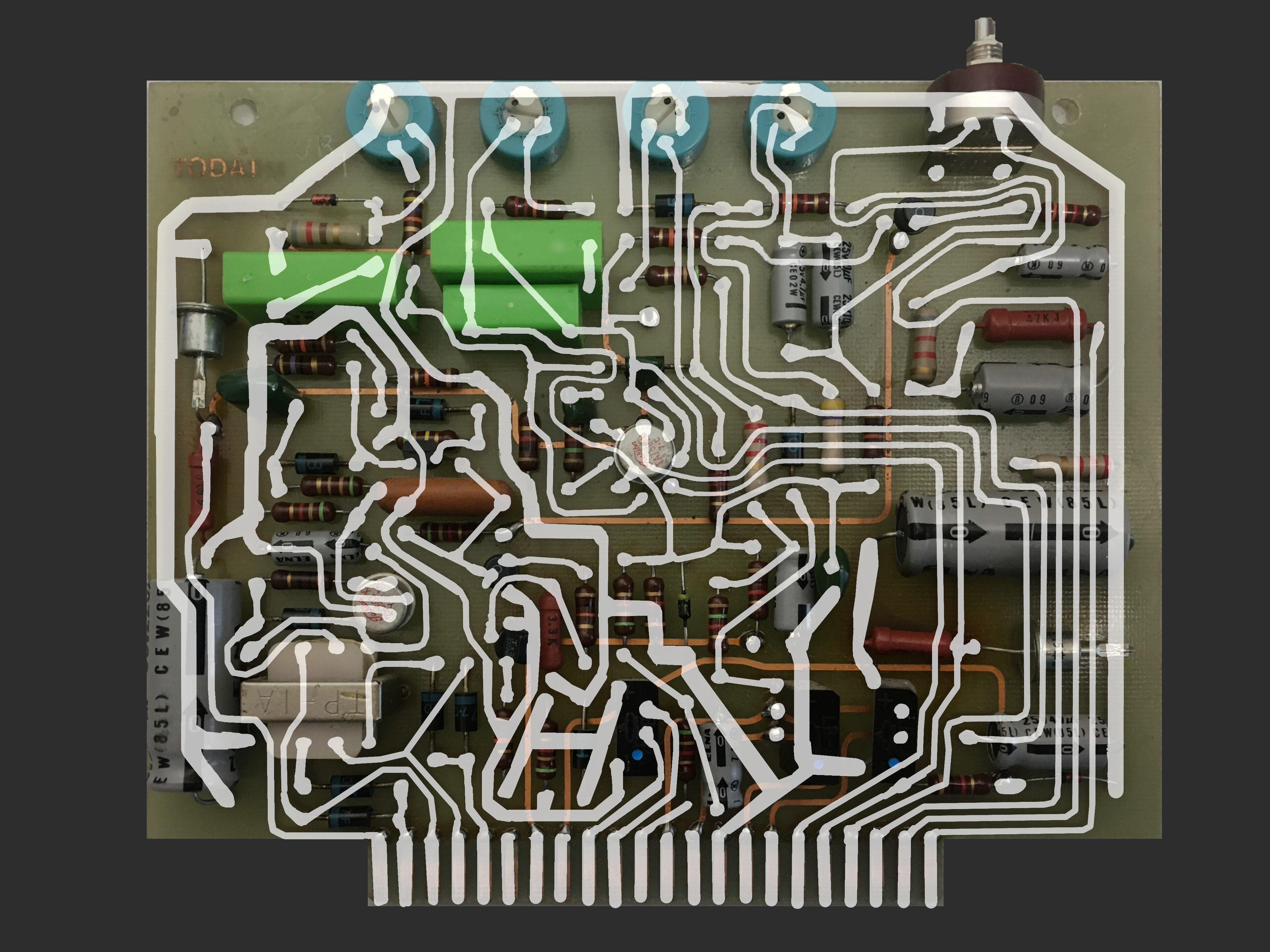
Since I was sure I was giving the rotor control board correct inputs, the rotor power components were new and wired correctly, and the stator was on, I figured there had to be a safety interlock turning my rotor off. I thought it made sense since the rotor could easily burn out if the motor ran in an incorrect configuration, so I diagrammed the whole rotor control board. Here are some pics of that process so you can admire the hand-drawn, artisanal PCB layout of mid-1970s Japan.
Here's the resulting schematic, it's confusing as hell. I also drew it slightly wrong, so there was an iterative process here of trying to understand the design, deciding there's no way that portion makes sense, and realizing it wasn't actually connected like that. The worst instance of that game was when I missed a sneaky diagonal connection across the whole board which links the two power supplies' grounds together. For a long time I thought it had two isolated positive power supplies for some bizarre reason, not a single power supply with positive and negative legs.
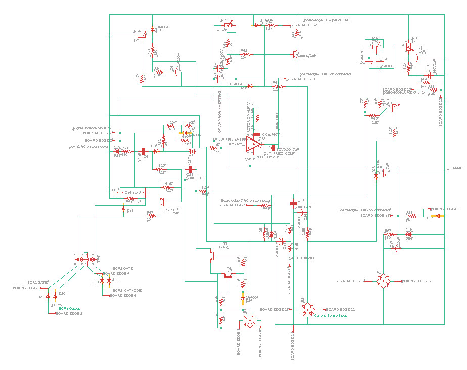
The short version of this board's functionality is that it's got a +11V power supply and a -11V power supply each of which is just a rectifier, some caps, and a big fat zener diode. I'm not sure if they're using zener shunts to regulate just because it was easy, or if there's some bit of 1980s lore here like perhaps zeners offered more stable voltage than early switching supplies. The third power supply looking affair doesn't have a zener because it's actually rectifying the output of a current sense transformer on one input to the rotor drive. That current sense signal is compared with an op-amp (hence the dual power supply) to the 0-11V speed signal which has been smoothed with a cap and voltage divided down to 0-3.3V with another zener clamping it to that range for good measure. The op-amp has some schmitt trigger logic and a bunch of frequency compensation stuff I don't understand (?) but its output runs via a weirdly complicated series of transistors to eventually power a little isolation transformer which outputs two floating voltages that get put across the cathode and gate pins of the two power SCRs. I think all the extra transistors and capacitors I don't understand are effectively integrating the current sense signal and dumping that sum each half-wave.
I stared at this circuit for a long time but I didn't see any interlock-like functionality, so I moved on to diagramming the rest of the machine and looking for interlocks there.

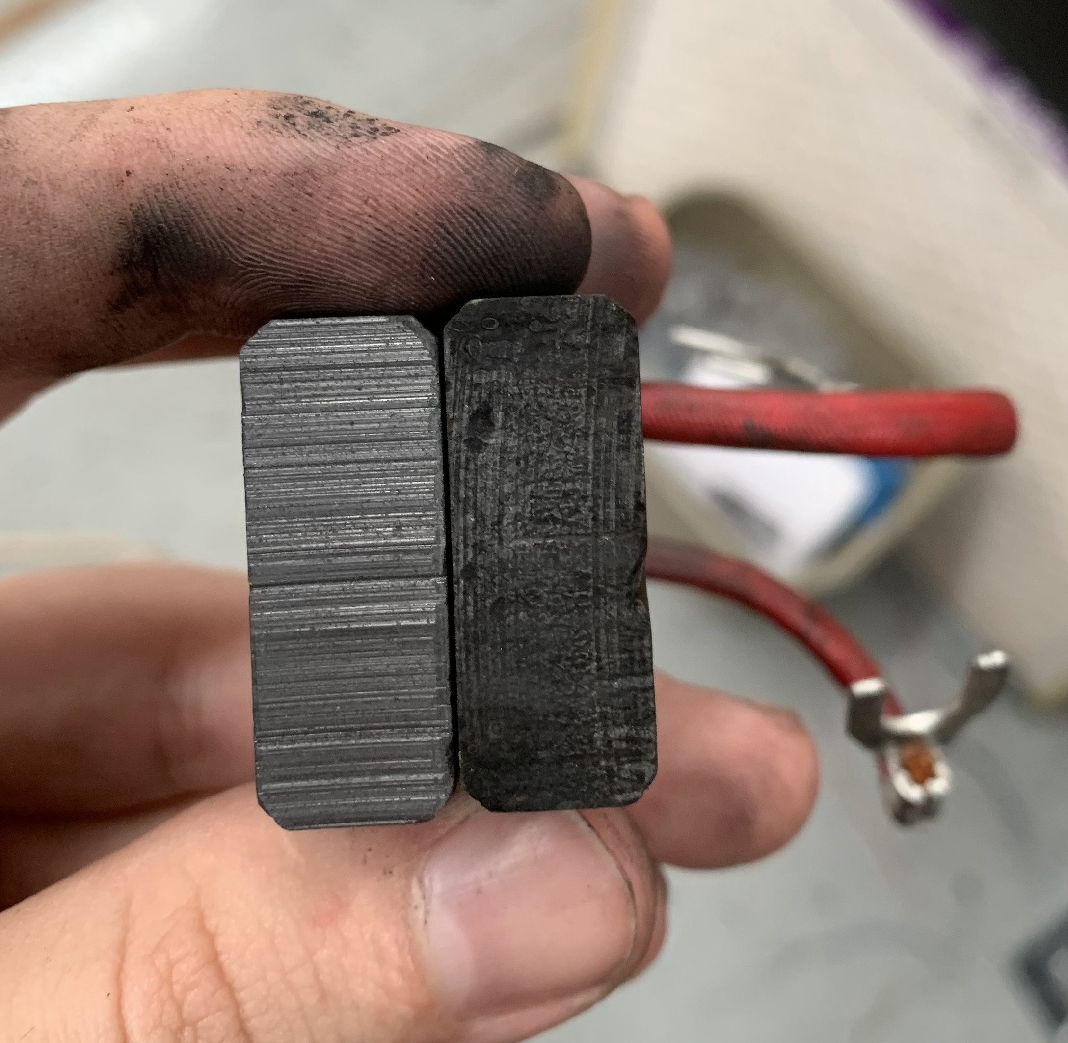
On a whim, I had brand new graphite brushes for the motor and I figured maybe those were bad in some way so I swapped them, to no effect. Stiff springs press the brushes against the rotor's commutator and make electrical contact with the commutator patches which are wired in an alternating fashion to turn the DC voltage applied across the brushes into appropriately phased AC in each of the rotor's coils.
Now's a good time to mention that the stator power supply is incredibly poorly mounted. It faces inward on a bracket, and there's a very important terminal block on the other side of that bracket, so you end up with this inaccessible board cocooned in high voltage wiring. I couldn't even get a good look at it so I called it the 'mystery board' for the first few weeks.
The 'mystery board' was clearly connected to at least one interlock: It powered one of the relays behind the rotor control board which could interrupt my speed signal. I did some major surgery to detach it from its mounting bracket without undoing too many wires, got several pictures along both sides of its length and eventually convinced myself that a) it's just a rectifying power supply for the stator and b) the only logic onboard checks that the 240V is drawing enough current then enables that relay.
Fairly well stumped, I finally decided to merge all of my diagrams and try to understand how 'spindle enable, rev on, spindle off' could be starting my motor. I put probe wires on all the relevant pins plus some unused pins of relevant relays and started pressing one button at a time then probing them. That didn't really go anywhere, but something fascinating happened: I accidentally tried to measure the voltage on my speed input pin using my meter's diode continuity test mode - which applies a voltage of up to ~1.5 volts but with high impedance - and the motor kicked on! It wasn't consistent, but when it failed I could just spin the spindle to a new position by hand and try again. Weird right?
That had me stumped so I bugged Dad and he was a) stumped too and b) annoyed at me for poking a live, fairly high voltage circuit with continuity probe mode on his expensive meter. Which, fair.
This mysterious behavior renewed my interest in what exactly the ground reference for my 0-11V signal ought to be. Maybe it lost a tie to neutral or ground when I was fixing the whole "the chassis shocks you when touched" problem? In the factory-original system the positive leg of the op-amp power supply was routed across the front potentiometer and so the ground reference was op-amp ground which was simple and reasonable. The retrofitters disconnected the positive lead, made their own power supply from AC up in the Bandit controller box, and ran a floating 0-11V signal back down to the spindle box in these two wires which they hooked up across the original potentiometer. So the front knob actually still worked, but it adjusted between 0 and your commanded speed instead of 0 and the system maximum.
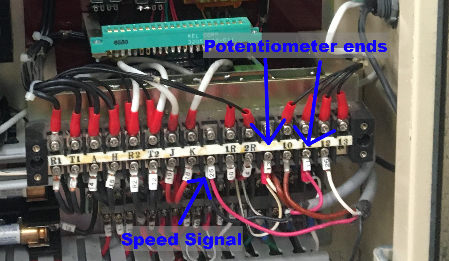
That meant the ground reference should still be op-amp ground, and sure enough one leg of the 0-11V signal was tied to op-amp ground. I measured the speed input pin from the correct ground reference for the first time - every previous probe was relative to the low side of the three potentiometer pins - and the speed input pin was at -5V. The amp had dual supplies so that didn't seem utterly crazy, maybe the current sense came in negative too for whatever reason. But then I noticed this zener diode:
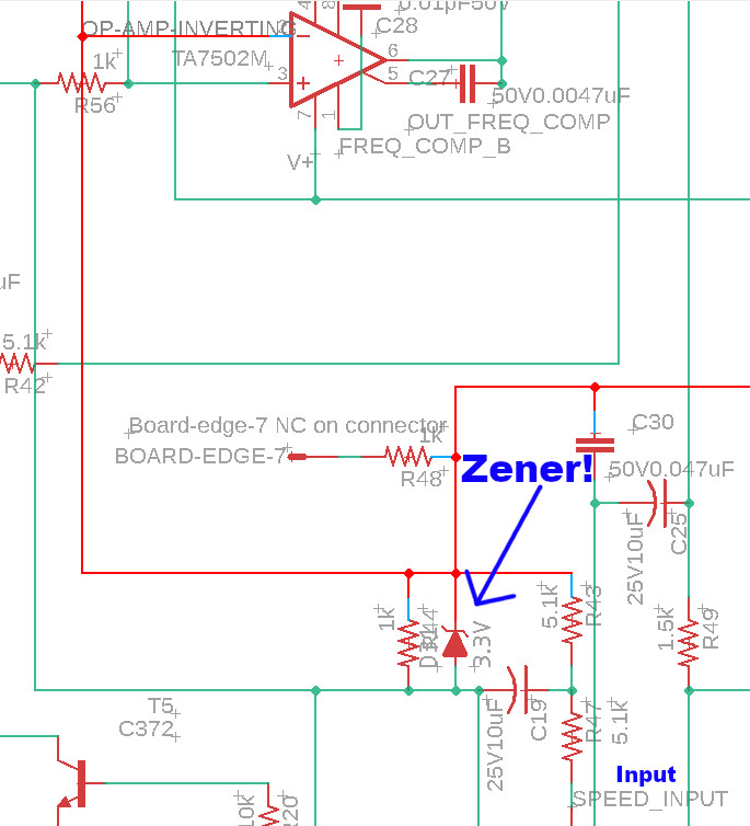
A negative voltage running past that zener would get clamped to its forward bias, -0.5 volts or so. That's throwing away all my signal! Then it hit me: What if I flipped the wires. What if sometime over the years when I was working out how to put 0-11V floating DC into them, or maybe when I fixed the ground issues, or who knows when, what if I flipped the two wires putting voltage across the potentiometer?
So I flipped them back and it worked. I still had to spin it by hand when it would get stuck but 3 out of 4 times I punched in speeds and it would start. I had direction control, I could spin fast or slow, it worked.
How horrible is that? A month of reverse engineering for some flipped wires. I lived with the inconsistent starting weirdness and finished my retrofit: a $20 isolation board that passes frequency-multiplied PWM through an isolation transformer to send 0-11V signals from LinuxCNC, some IO pins hooked in to imitate the wires with a 74ls04 to sink a bit more current, and I had full on spindle control.
Fixing My Other Mistake
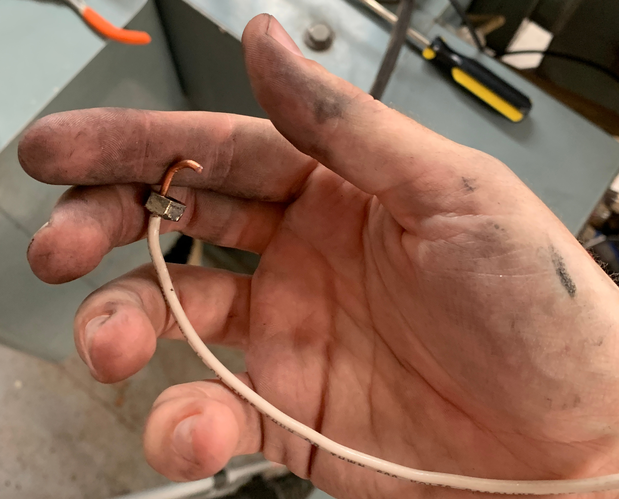
That intermittent starting? Also my fault. When I replaced the brushes one of them took a bit of shoving to get in there, and I didn't consider that the things are supposed to slide back and forth smoothly to keep good contact. They're spring loaded because the commutator ring they make contact with probably isn't perfectly centered, plus the graphite wears down. When I popped the thing open I couldn't pull one of them out at all - I thought I was going to yank the wire out of it. Eventually I unmounted its housing and shoved it out from the front. Here's what they looked like - the good one on the left had a nice wear pattern from rubbing on the commutator and the stuck one had a rough finish like it was brand new.
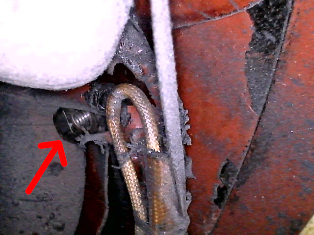
For good measure I made one last mistake and dropped a nut which holds the brush's spade connector onto its power lug into the motor. The motor had pretty tight openings to access the brushes on either side, so that took a couple hours of fishing with a boroscope and some wire to fix:
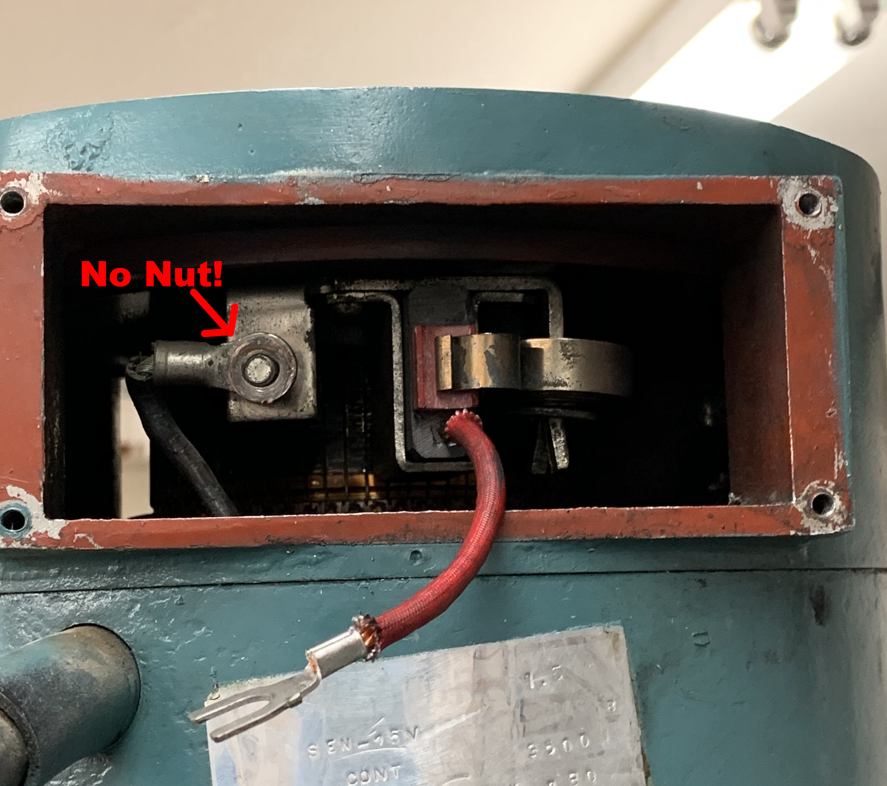
But I got it out eventually, and as of now this ~45 year old 3 HP spindle motor purrs happily.