We left off last time with a fully functional mill! Right? I've got motion control, I've got reliable spindle control, life is good!
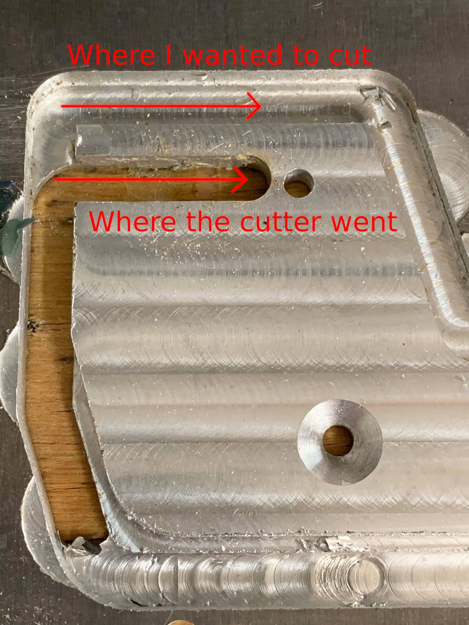
Well, no. I was trying to machine some 1/4" aluminum to replace a piece of the tilt axis on Praxis's prototype five-axis 3D printer and under fairly modest tool forces the Y axis lost a ton of steps, a corner got cut short, and my cutter plowed through a key region of the part. Wups!
A stepper motor "loses steps" when the coils can't pull the next tooth of the rotor hard enough to overcome the torques being applied to the motor. When that happens the rotor simply doesn't move, which might sound OK except it never recovers. The advantage of stepper motors is that you always know where they are because each command moves them a fixed distance. Most electric motors only have control over their power, so how far they turn depends on the load and you need feedback sensors to move them accurately. Steppers will always be exactly where you tell them to be, unless you overload them and lose steps, and then they'll be incorrectly positioned by a fixed distance until you reset them.
That led to some closer inspection which showed that my steppers, which nominally would be stepping through eight coil states based on the half-stepping table I put in the LinuxCNC firmware, were running a nine step table. 8 steps forward, then a twitch, then 8 more steps forward. What the?
I spent far too much time watching two channels of the drivers' inputs or outputs at a time using my oscilloscope and eventually convinced myself the thing was working as I expected - each pin controls one phase, and I was stepping through them in the right order. My firmware was just doing spurious things at the end of every cycle through the table.
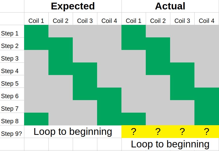
If I changed the number of entries in the table, same behavior. One extra state with undefined behavior no matter how I configured it. Even if I changed the table to just power the same pin in every state, there'd be an extra state where it did something else.
It seemed for all the world like someone had made an off-by-one mistake in LinuxCNC's table mode and I was getting one byte of completely random data each cycle, but this project dates back to the 90s how could it have such a simple bug?
Turns out that's exactly what it was, and in a bizarre twist their fantastic maintainer PCW (who has helped me personally numerous times, and seems to always be on the forums) had fixed this bug the week before I figured out it was screwing me. One update to the dev version later and life was good. The eight state table got me eight steps with no jitter.
Just kidding! The jitter was gone, but I still couldn't hit the speeds the original bandit could, and my motor drivers were getting seriously toasty. I used the mill in this state for a week or so but it was still losing steps, particularly on the Z axis, presumably due to driver overheating. I started planning to clone the drivers with modern, much more efficient mosfets.
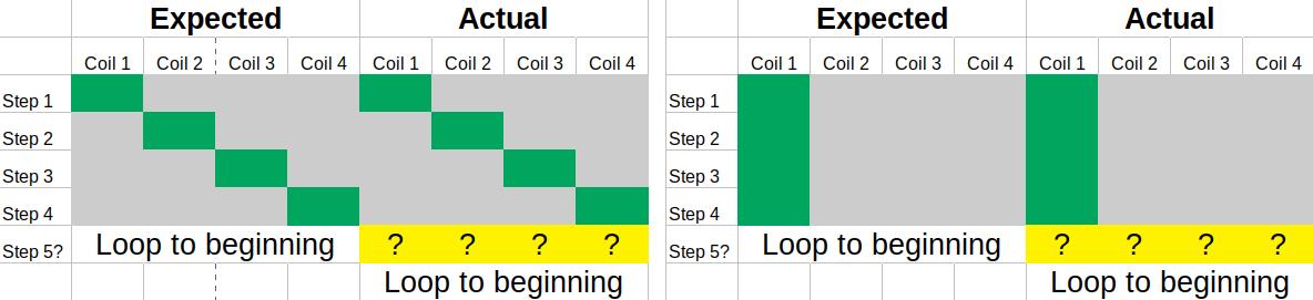
Fortunately before I jumped down that rabbit hole I took one more look at my circuit and realized somewhere in all my confusion the table got inverted: The FPGA card which generates my step signals has pretty wimpy current limits so I run them all through a 74ls04 hex inverter. The stepper drivers are active high, so with an inverter between them I needed to put a zero in my bit table where I wanted a coil activated.
My original table from High School did just that - it was the bitwise inverse of the table I entered after updating LinuxCNC, but I forgot that detail in the switch and amazingly the steppers still functioned in that mode. Instead of alternating between powering one phase and two phases in traditional half-stepping, I was switching between three phases and two, but since they still progressed around the motor in the right fashion the step directions and sizes all worked out.
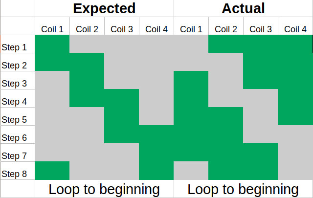
After fixing that I had one last issue where my step resolution was still configured for the 9/8 scaling caused by the off-by-one issue so I cut a couple parts 11.11% smaller than I meant to, but I spotted that after a couple days and this thing finally, actually, works.