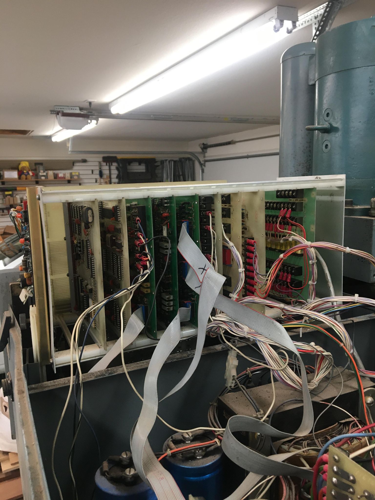
The next phase of the project was moving the system off the original Bandit controller onto something that could talk to modern CAM packages. The Bandit is a beautiful piece of computing history: 7 cards of hand-soldered through-hole 76 series logic mounted to a backplane, but 1000 program lines rules out significant surface profiling, and the old dialect of gcode it runs would have taken a lot of fiddling to make teach a CAM package to output.
I ended up using LinuxCNC to run the system off an ancient desktop tower. Running a stepper or servo motor controlled machine is a mix of fairly soft realtime and hard realtime problems: Deciding where to go, computing the velocity and acceleration curves, and controlling all the auxiliary functions like the spindle, coolant, and tool change system, can all be done with milliseconds of latency. At that level just about any modern computer will keep up without any trouble. My system has 1 GB of ram and a mid-2000s Pentium 4 processor, and that does the job.
On the other hand the motor drives need to receive a pulse for every 0.0005 inch step the axes take, which works out to about 3 kHz signals for my machine's top speed of 100 inches/min. Other people in the LinuxCNC community generate signals much faster than that from userspace software, but you need to carefully tune your system to eliminate latency spikes, and part of that is obtaining an antique computer with the right low latency chipsets. I didn't want to do all that, so I bought a Mesa 6i25 FPGA card for ~$100 which slots into the computer's PCIe slot like a graphics card.
In my system the userspace software tries to run 3 PID loops at 1 kHz. Each PID loop controls the velocity command sent to the FPGA for one axis based on the difference between the intended position of that axis and the last position reported by the FPGA. Occasionally the PID loops' frequency will drop a little if the computer is busy with other tasks, and that's alright because the FPGA is handling all the truly high speed work.
Old School Stepper Motors
The other interesting component of my mill's motion system is that the stepper drivers don't have step and direction inputs like modern drivers.
Think of a stepper motor as a little magnetic gear with electromagnets arranged around it. When we turn a magnet coil on it tries to pull the nearest gear tooth to center on it, or if we turn it on with opposite polarity it pushes the two nearest teeth away and tries to center the valley between them. In reality hybrid stepper motors are built as a pair of coaxial "gears" half a tooth out of phase, but the effect is the same. If you choose the number of teeth and coils correctly, you can ensure there's always a coil to turn on to move the gear a discrete distance in either direction. The widely used interface to control these systems uses two pins called step and direction, where one pin is pulsed every time you want to turn one discrete 'step', and the state of the other pin indicates which direction that step should go.
Most modern stepper motors have just two sets of coils, and they use H-bridge like drive circuits to drive them with both polarities. This is the minimum viable stepper if you want to be able to turn both directions. In full-step mode the driver rotates through a four state table of coil polarities. Driving powerful coils in both directions is a little bit tricky because you need to handle back-emf in both directions when they turn off, but it's drop dead easy commodity hardware today. Modern drivers go beyond that and 'microstep' motors by precisely varying the current across the coils to pull the gear a fraction of a tooth in either direction.
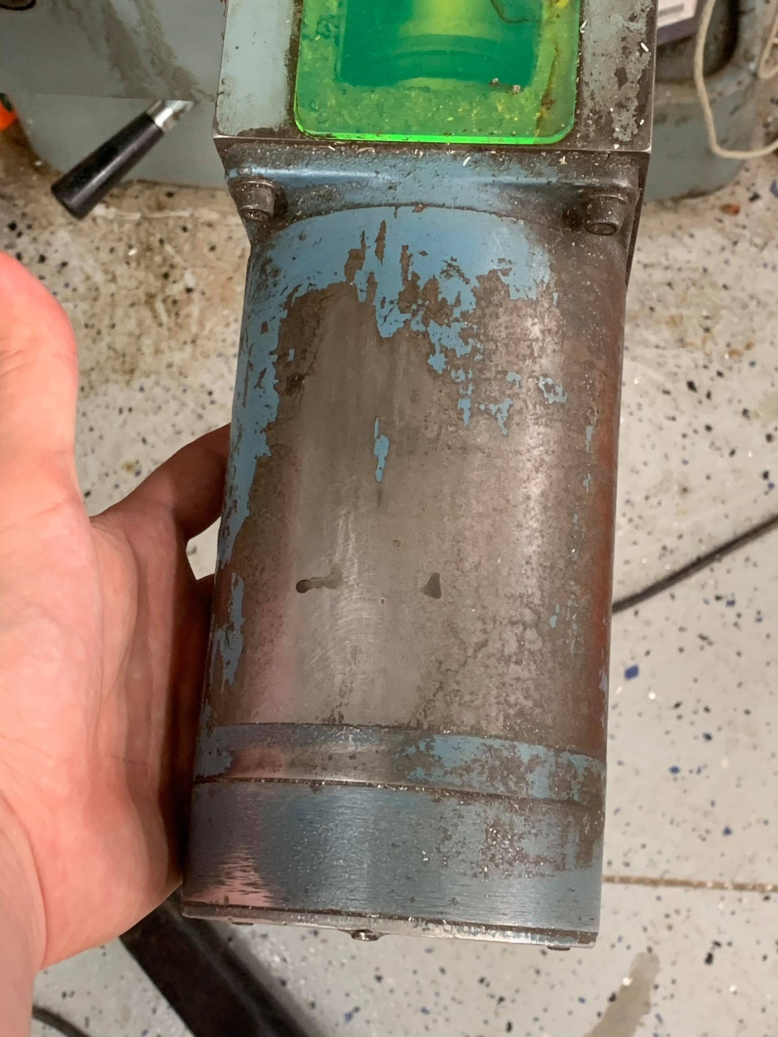
Apparently around 1980 transistors cost more and coils cost less, because my stepper drives don't bother with all that. Instead, the motors weigh 18 pounds and each contain four unipolar sets of coils. With four coils the arrangement of the motor is much easier to visualize. At each full step position one coil is powered and its two neighbors have teeth pointing off to one side of them.
That's how mine work, and instead of a step/dir interface which would take extra logic, the drivers simply have four 5V input pins for "turn this coil on." I hooked those up to the FPGA's outputs and configured the firmware in 'table mode' to cycle through an 8 state table of bits for half-stepping, where instead of turning one coil on at a time you turn a coil on, then turn its neighbor on to move a 'half step' between the two, then turn the first coil off for another half step, which doubles your resolution and also increases torque.
I sorted all this out as a kid and had my old PC moving the axes around by the Summer of 2014. Unfortunately that's all I managed to do before leaving for a summer at Rice and then starting undergrad at Cornell. Without a connection between LinuxCNC and the spindle driver the machine couldn't make anything. It sat idle for years while I was away in New York, and I think my Dad nursed a growing resentment over the lost garage space.