Servo-Pistons
In the first year of the pandemic I got obsessed with diaphragm pistons. I encourage you to go read the Exciting Tech page first if you haven't heard my spiel about these things before, but the TL;DR is "one-way-acting pneumatic or hydraulic pistons with negligible friction/stiction, and ultra-loose tolerances which enable cheap construction." They're great little devices. The two main downsides are that the seals can handle maybe 1/10th of conventional hydraulic pressures which means you're sacrificing max force in exchange for these advantages, and the seals themselves are fiddly to produce in long aspect ratios, but as I'll explain below there are viable manufacturing methods to solve that.
While stuck at home with my dad's luxuriously equipped workshop for wood and composites, I think I advanced the state of the art somewhat. I'm not pursuing this concept professionally because novel robotic actuator startups are a brutally hard business, but I think this could be a fantastic phd project for somebody, and might be an awesome unlock for open source robotic arms. If you're interested in adopting this project, please read to the end because I'd like to support you. This post is a bit messy because I did this work 2.5 years before writing it, but here we go!
Let's Use Carbon Fiber
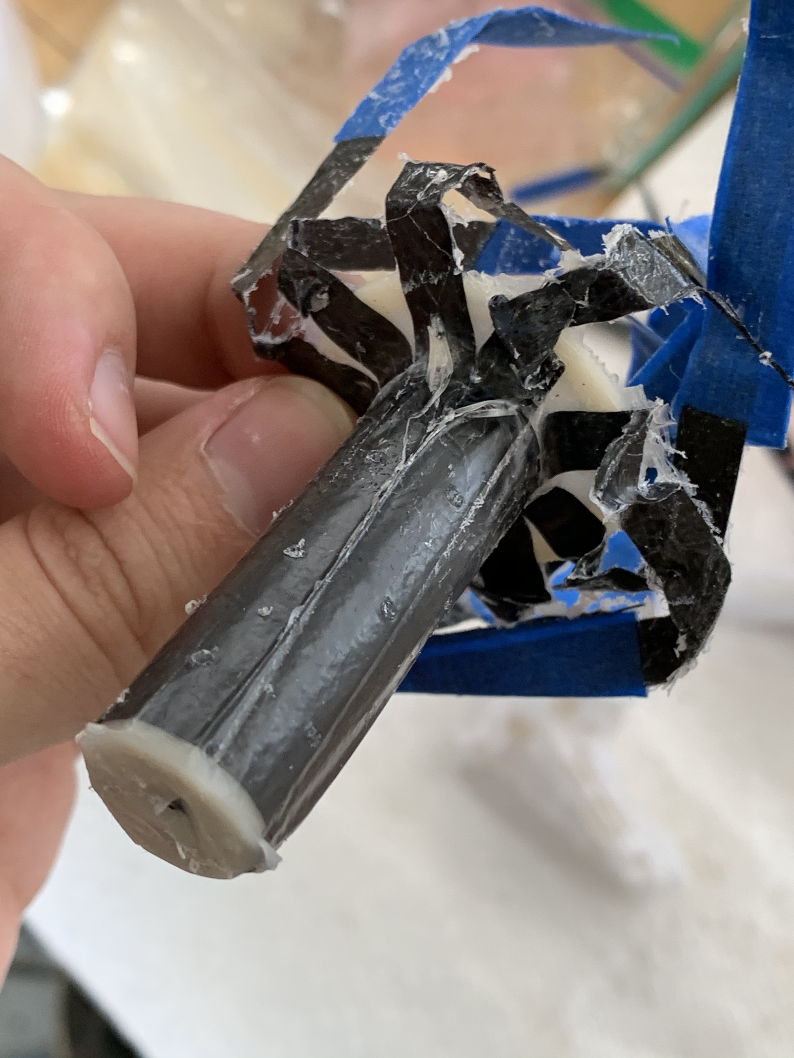
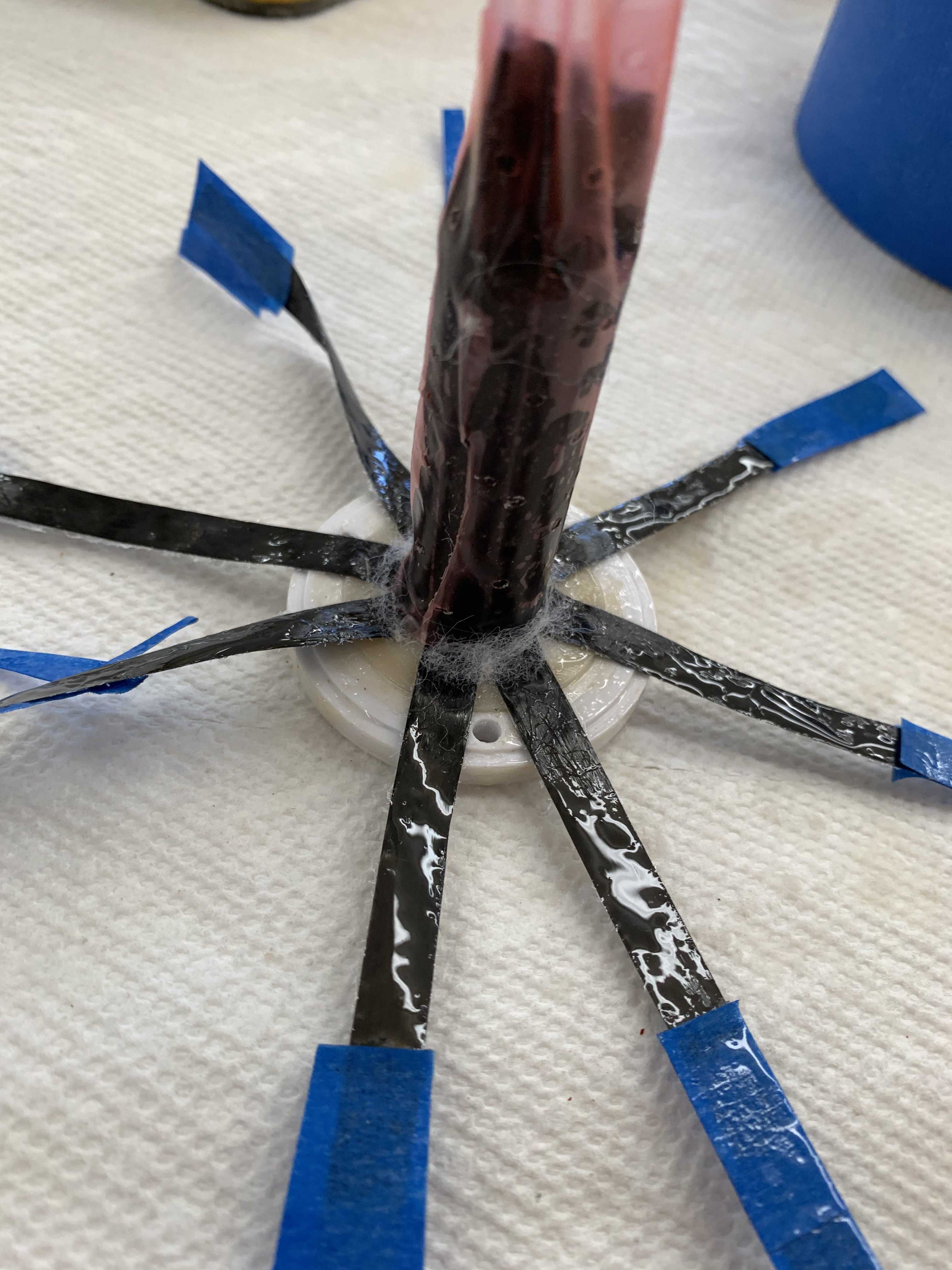
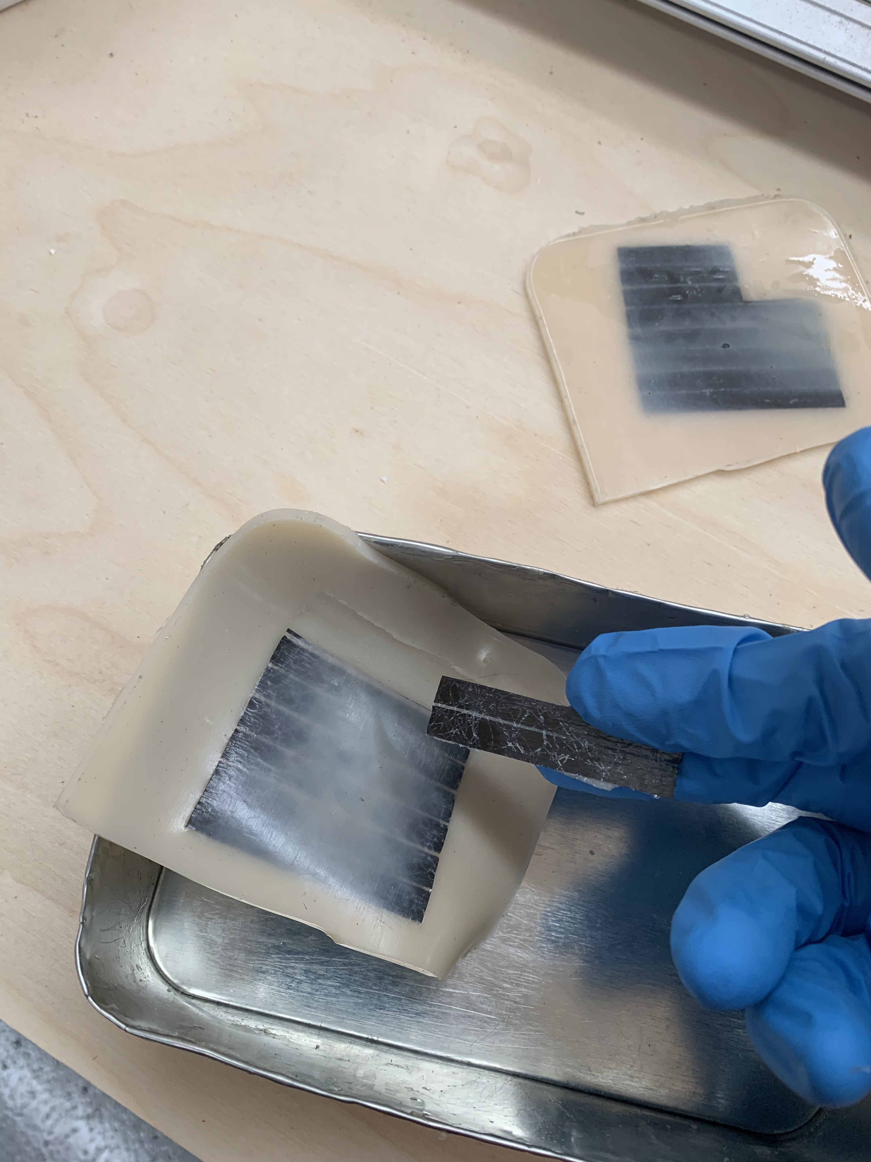
Diaphragm seals need a reinforcing layer which is strong and stiff axially, but stretchy diametrically so the seal can expand from the inner bore diameter to the outer bore diameter. The original paper I tried to replicate used woven sil-nylon cloth as the reinforcing layer, but normal cloth is stiff in all directions so they lasercut tiny patterns in it to cut all the fibers in one direction and only most of the fibers in the other direction. Instead of doing all that work with a lasercutter, I used fabric which only had fibers in one direction right off the shelf. Specifically, unidirectional carbon fiber meant for composite layup. This turned out to be far more work because the sil-nylon bonds to silicone nicely while carbon fiber really doesn't like adhering to elastomers (or anything) without some dark magic chemistry (compatibilizers! reactive ion etching!) I didn't have access to, but I managed to make some usable enough diaphragms from ACP composites carbon fiber and Smooth-on two part urethane rubber, so live and learn right? It was a lucky choice despite my adhesion issues, because carbon fiber happens to be conductive.
The seal is the sensor
My most original contribution in this project is using conductive reinforcing fibers to create a capacitor between the diaphragm seal and the housing of the piston which has linearly varying capacitance with respect to position. My extremely fly by night prototype (see video) could already sense position with about 0.5 mm accuracy, and I think there's a clear path to at least 20 micron resolution. I also suspect the capacitive reading is weakly dependent on force because the 'donut' portion of the seal can stretch and get very slightly more area close to the outer bore, so an antagonistic pair of pistons would likely be able to measure both position and force by diffing the two position readings.
How exactly does this work?
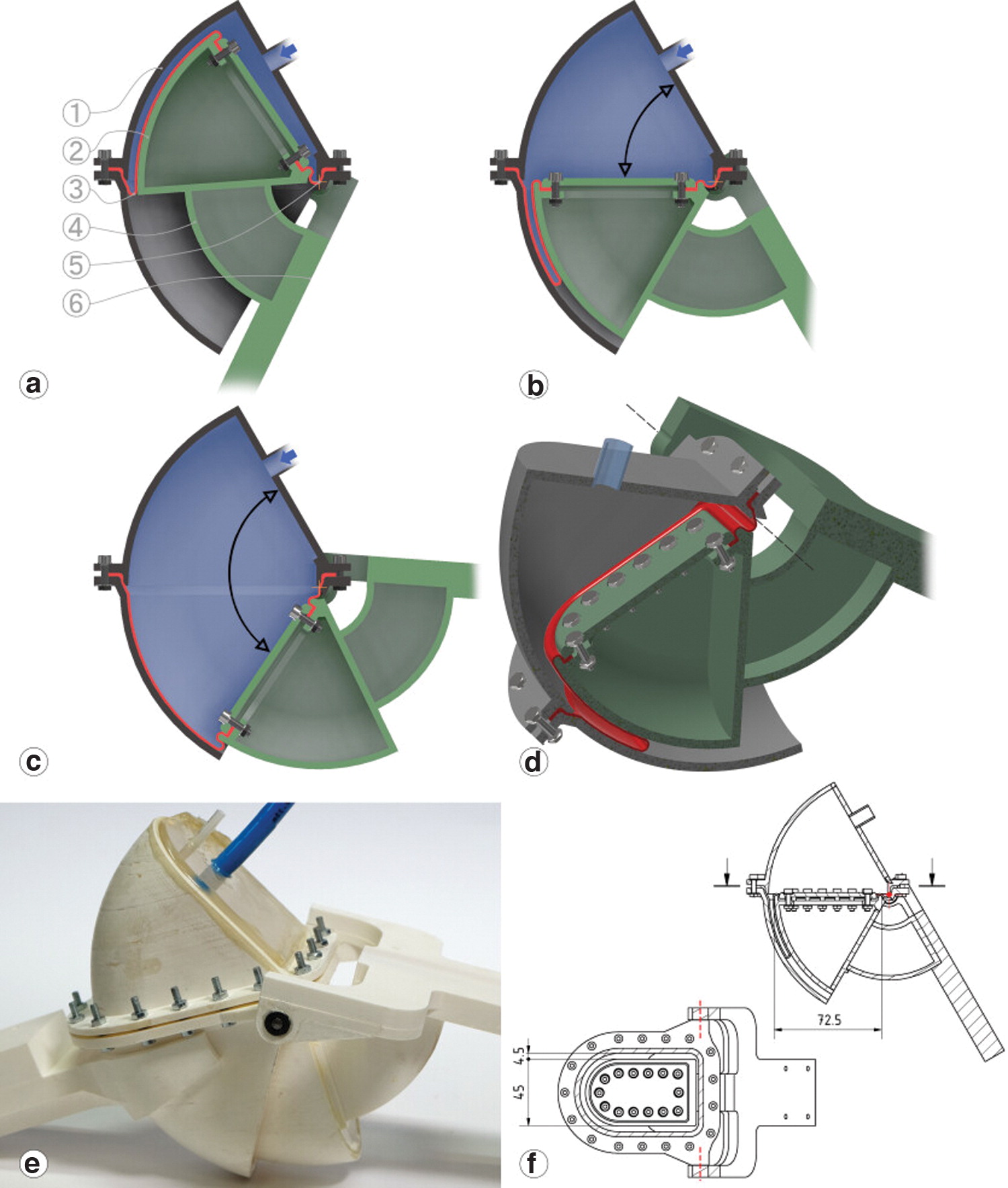
Before continuing, stare at the diagram below for 15 seconds and imagine moving the inner bore (the grey box centered on the dashed midline) left and right. You should visualize the red and blue diaphragm rolling off the inner bore and onto the green outer bore as the inner bore moves right, and vice versa as it moves left. If you can't imagine it, think about taking off a really tight pant-leg or shirt sleeve and how it turns itself inside out, then try again. Got it? Good. If somebody wants to animate this for me please reach out!
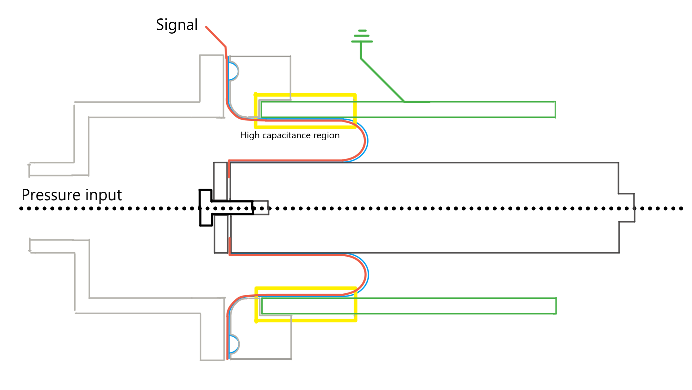
The diaphragm seal has a fixed length along its axis, and as the piston moves that length gets shifted from the inner bore to the outer one and back. When pushed all the way in ~90% of the length is on the inner bore and the remaining 10% is in the "donut", and when extended all the way out ~90% is on the outer bore. That means the length of diaphragm pressed against the outer bore is linearly proportional to the piston position.
The capacitance between two conductive surfaces is proportional to area divided by gap distance. In the "high capacitance region" highlighted in yellow, the diaphragm is pressed against the outer bore by the pressure so the gap distance is ~0. To keep exposed fibers on the surface of my poorly cast rubber diaphragm from actually touching the aluminum, I put a layer of 0.03 mm thick kapton tape (not pictured, sorry) over the entire inner surface of my aluminum tube. The clearance between the two bores was something like 5 mm, so a given patch of area on the diaphragm contributes ~150x more capacitance when it's pressed against the outer bore than when it has rolled onto the inner one. The capacitance is also decently large: for a 20mm bore diameter it's about 60 picofarad per millimeter with kapton as the dielectric, and bigger pistons give bigger capacitance signals.
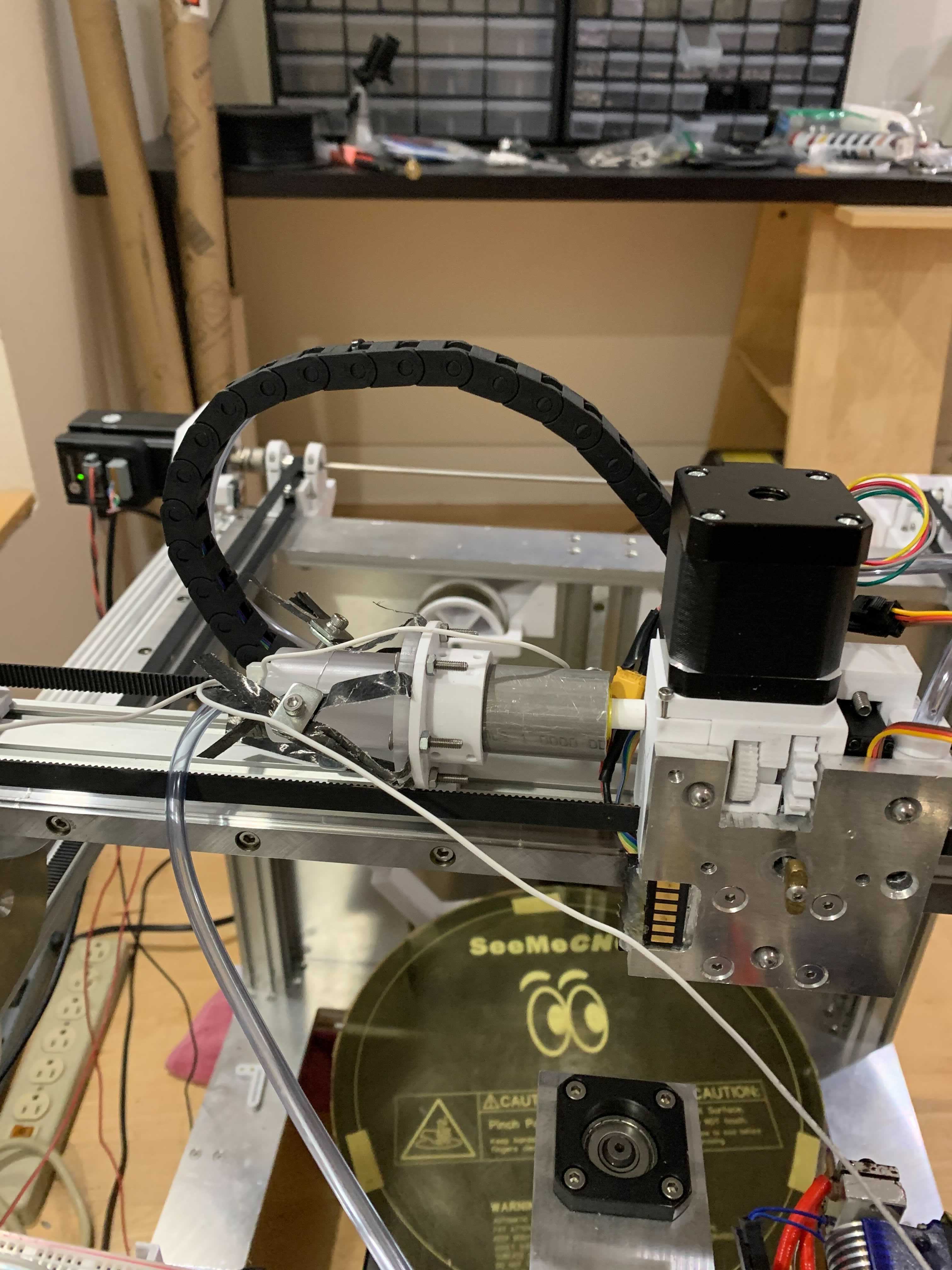
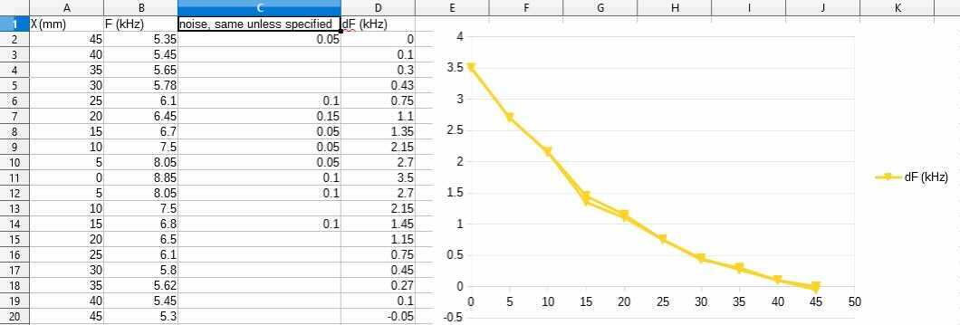
I mounted the awful piston from the video on the X axis of one of my 3D printers and measured the frequency of my awful RC oscillator for a range of piston positions first extending the piston then compressing it again to check for hysteresis. The piston was pressurized very roughly to 8 psi by a $30 aquarium pump with no reservoir, so it had an awful amount of noise from the pressure alone. Despite all that I got a very clear position reading and no measurable hysteresis. Apologies again for the poor presentation here, I'm pulling from images and video I quickly captured to share with friends - I intended to do prettier tests and make a video about this eventually, but I got busy.
This is about as far as I got unfortunately, so I'll take a few paragraphs here to go through potential and pitfalls with this idea before wrapping things up. No more fun test data beyond this point.
Why am I so confident the resolution can be improved?
Capacitance measurement is really mature technology. For example, the FDC2212 is a $5 chip which will happily give you 10-12 useful bits at kHz sample rates, then dial into 20+ bits of resolution if you give it a fraction of a second to settle. The capacitance signal from these pistons is large, and with good mechanical engineering it can be made clean. The grounded outer bore acts as a faraday cage and shields the sense element (the diaphragm) from stray capacitance, and if you want even more signal for some reason you can 20x it easily by coating the outer bore in a dielectric ceramic like those used in cheap ceramic capacitors.
Where should we use servo pistons?
I think the best answer is probably robotic arms and humanoid robots. The pistons are single acting because you can't invert the pressure on the diaphragm without messing up the rolling action, so they badly want to be used in antagonistic pairs. There are mildly rube goldberg ways to package a pair end-to-end into a single double-acting piston, but the piston length to actuation length ratio is pretty awful in every design I can think of. The Disney Research teleoperation demo using sensor-less diaphragm pistons shows how simple it is to actuate rotary joints with these, and if not for their usual stiction/accuracy issues hydraulics would be an obvious choice for robotic arms because they get your power plant off the moving mass budget without doing any weird transmission tricks through the more proximate joints.
Their dynamic range, torque, and power densities beat state of the art
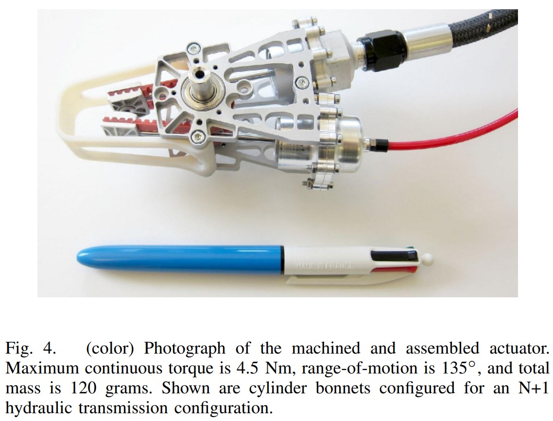
The Disney rotary actuator shown above already has better torque density and top speeds than harmonic drive servos, and my servo piston proposal adds integral sensing to that. Plus, if my schemes to economically manufacture them with longer aspect ratios work, the disney papers claim that could boost torque density by an order of magnitude.
The first author John P. Whitney has more recent papers (no longer with Disney) showing some seriously impressive performance, plus a neat trick to do double acting without introducing any static friction issues.
Their packaging is extremely flexible
Unlike conventional pistons with tight clearances between their bores, servo pistons (and all diaphragm pistons) have several millimeter gaps between their bores to give the diaphragm room to turn around without bending sharply enough to cause fatigue/rubbing issues. Rectangular or arbitrarily shaped bores, curved pistons, tapered pistons, and more are all viable options for the packaging-constrained roboticist. These more 'designer' variants will be annoying to calibrate the sensor output on, but the core ideas all still work. If you want to get really weird, there's nothing stopping you from using flexible tubing as the outer bore and making a strange, much more controllable, buit-in-sensing alternative to a Mckibben muscle.
They're tunably stiff which is great for cobots
Servo pistons are teachable systems. If you take an antagonistic pair of servo pistons and connect their pressurized sides with a needle valve you get a tunably stiff system. With the valve wide open the system is easy to move because pressure in the compressed piston quickly shifts to the decompressed piston, but as you close the valve the pressure difference for the same movement speed increases, until in the closed state you get the full stiffness of your working fluid, which can be incredibly rigid if you're doing hydraulics not pneumatics. The Disney Research paper has a lot of great figures on this approach and the achievable system dynamics.
Since the pistons are also sensors, you can record trajectories in this reduced stiffness mode then play them back with full force. Or if your pump system has enough flow to keep up, you can open the needle valve during controlled movements to 'force limit' the robot so it can't crush people or objects by accident.
They're lockable
I originally got interested in fluid robotics because I wanted to make a body-powered prosthetic arm that pulled hydraulic power from a shoulder harness and used it to actuate multiple degrees of freedom in a hand with a small electronic valve complex to switch which actuators were connected to the pressure depending on the intended grip function. One really nice capability of all hydraulics is that they can hold position with very little power: If you just close the valve to a piston, the incompressibility of your fluid makes it rock solid. I mentioned in the intro that I think these things will be able to measure force by comparing the capacitance readout from antagonistic pairs; If I'm right about that, robotics applications could pull an excellent trick where they lock the robot's "stabilizer muscles" and spend ~no power on them, but monitor the force balance on the joints and unlock them to apply corrections only as-needed.
How do we make them?
The easiest prototyping method I found was to screw a cap onto the positive mold which clamped the edge of the uniaxial fabric to the tip of the mold, fill the negative mold with urethane, then push the fiber-wrapped positive in and throw the assembled mold in a vacuum pot to remove bubbles. After curing I used a heat gun to melt my negative mold (made of PLA) off the diaphragm/positive mold (ABS), then disassembled the flanged part of the inner mold which was held on by screws and used the rod shaped part of it as my new piston's inner bore. Since I never quite solved the carbon fiber <> elastomer interface chemistry problem, this approach positively retained the fiber to the inner piston and prevented an earlier issue I had where the fiber would work its way free of the elastomer and start peeling off.
I think the right way to make these is to lay the conductive reinforcement fibers up on a mandrel with appropriate compatibilizers already impregnated into it and then dip the mandrels into heat-set rubber similar to a condom manufacturing line. Since this project I've met a lot of brilliant polymer chemists through my role at AON3D, and a few of them have mentioned nitrile chemistry would likely be more willing to bond to carbon or other conductive fibers than urethane. I originally started this project with silicone, which was a horrible choice because that stuff bonds to nothing.
Someone with more time than me should also dig into the optimal reinforcement material. The main constraints as I see them are:
- Keep them conductive enough for the capacitive sensing trick
- Maximize adhesion between the rigid reinforcement and the elastomer
- Keep the final diaphragms stretchy enough in diameter to go from the inner diameter to the outer diameter
- Avoid insanely fiddly assembly/production
- Avoid materials with fatigue issues
I think 2. and to a lesser degree 1. push strongly away from carbon fiber. Carbon fiber is cool and you might want to keep it for marketing value if you build a startup around these, but it hates bonding to stuff. I've spent entirely too much time reading obscure composites papers trying to find a 'magic bullet' here that would justify reviving this project with carbon fiber, but I don't think anyone's found it yet. As far as I've been able to find, uniaxial fabrics made from fine metal wire don't exist for any scaled industrial application that would make them available in prototype quantities like the carbon fiber I've been using. The same manufacturing methods which produce carbon fiber fabrics would work with fine metal wire, but those are expensive machines and nobody wants to build a specialized miniature one for a project like this.
Expandable sleeving
The whole time I was working on this project in meatspace (as opposed to writing it up now, 3 years later) I had one extra constraint: "the diaphragm can't shrink axially when stretched in diameter like a Chinese finger trap." I somehow got it in my head that such 'poisson ratio' behavior would break the pure rolling motion of the seal and ruin things, but I realize now that it doesn't. The position of the piston is controlled by the difference between the length of diaphragm on the outer bore and the length on the inner bore, and nothing in the math forces the sum of those two values to be fixed throughout the travel. If your diaphragm has this behavior, you need to make it slightly longer to reach the same overall travel, but that doesn't have any knock-on effects about piston length : stroke length ratios or anything like that.
Without that constraint, the obvious choice of reinforcement material is braided sleeving. You can get it in carbon fiber if you want to follow my path of fighting awful adhesion chemistry problems, but you can also buy stainless steel, copper, polyester, PTFE, PEEK, and anything else you can imagine next-day off Mcmaster. Put that stuff on a mandrel, dip coat it, and call it a day! I'm a little worried the fibers rotating past each other as the sleeving expands will shear the polymer matrix an unacceptable amount at their interface points, but adding some carbon black and/or short chopped fibers to serve as rip-stop inclusions probably makes that harmless.
As of writing I have a Mcmaster order on the way to see how inverting these sleeves feels in real life, if it seems workable I'll probably try dip coating some in urethane.
Photochemical Machining
My current favorite "out there" solution is photochemical machining of spring steel shim stock. Photochemical machining is cheap even at prototype scales ($1000 min order gets you a dozen copies each of ~a dozen different design variants packed into a single phototool) and has "zero cost complexity" similar to 3D printing, but for ultra-precise 2D features in thin metal. If I were picking this project back up myself, I would order a sheet of different piston length x piston inner circumference rectangles with as many slots as I can fit packed in along the length axis, and various schemes of connection between the fibers at the ends / along their length to simplify installation onto the dip mandrels.
According to this awesome design guide bars can be 20% thinner than the actual metal thickness while slots need to be 120% wider than the metal thickness, so we get 1 bar or "fiber" every 2 material thicknesses in the diameter axis. In 0.025 mm shim stock that's 100 threads per inch, not quite actual fabric territory but more than enough for our purposes. If this material sounds concerningly thin, we can make the rectangles 2x or 3x circumference and put a few layers of metal fibers into our diaphragm instead of just one.
I think for ease of manipulation the right answer is probably to connect all the fibers across the "top" end where they just have to wrap around the tip of the mandrel, then connect the bottom ends into a dozen or so "bundles" which will splay out around the flared bottom and be secured into the sealing bead at the base of the diaphragm. The section of the diaphragm where the diameter expands to reach the seal seat never peels off the outer bore of the piston, so it's OK for it to have large gaps between the reinforcing fibers because it's not at risk of bursting. Here's an Onshape part sketching out roughly what I have in mind. There's definitely smarter ways to do it if you get to "how do I automate production of these" type questions, but I think this design would be fine for a grad student making dozens at a time.
Please build this
If you're interested in building this please reach out via twitter or email. I'd be interested in paying you a trivial sum like $25 for either written or zoom weekly updates on your efforts as an accountability mechanism to help you keep after it. No IP/equity/compensation to me of any form, just the satisfaction of knowing you, a person other than me, are pursuing this idea and I'll get to see how far it can go in the real world eventually. Or if you're a VC sufficiently in love with this idea, I'm not available but I have friends I could nerd snipe with the promise of seed funding ;)
Thanks Friends
Hanging out on Scope of Work (née The Prepared) was one of the things that kept me sane during the pandemic, and my posts in the #projects channel on there are the only reason this scheme has as much photo documentation as it does. All my friends on slack but in particular Richard, Surjan, and Kevin deserve credit if anyone ever makes anything of this scheme. If you don't have a community like this gently peer pressuring you to complete projects, I highly recommend it. Thanks also to Peter Whitney (one of the Disney authors) for replying blindingly fast to a draft of this post with great feedback!