This page is about how we might all have strong, fast, cheap, and capable robots in a few years. Skip the first two sections if you already know how gear systems work, what a harmonic drive is, and what they're good for.
Why Do We Need Reduction Drives?
One of the biggest roadblocks to ubiquitous robots is that electric motors are too fast. In the broadest terms, electric motors use magnetic 'traction' to move a rotor (spinning part) along relative to a stator (stationary part). Depending on the design, parts of the rotor and/or stator are electromagnets which get turned on and off based on the rotor position so the traction keeps going and the rotor spins continuously. At high speeds it gets hard to turn those electromagnets on and off fast enough, but up to that limit the 'traction' force is pretty much constant with respect to speed. The same force applied to a faster moving object does more work (force * distance), so electric motors make the most power (work / time) when they're running fast.
Robots are relatively slow. A quadruped's knee mid-leap or an industrial arm rapid-moving to the next work position might hit a few hundred RPM, but generally robot joints don't go faster than that. Electric motors like to live at a few thousand rpm. Robots want to be slow, strong, and accurate but motors are fast, weak, and sloppy.
Enter, reduction drives. Reduction drives are gear systems used in robots and other systems to reduce speed in exchange for greater strength, ie a perfectly efficient 2:1 gearbox would halve your speed and double your torque, or more frequently in robotics a 20:1 will output 5% speed and 20x torque. These speed reductions also increase the "resolution" of robots: It's very hard to wiggle a motor's electromagnets just right to move the tip of a long arm a fraction of a millimeter, but comparatively easy to spin that motor about 20x the intended distance and put its output through a gearbox with a 20:1 ratio.
The phrase "perfectly efficient" is doing a lot here. Real gear systems have imperfect teeth which slide against each other when they mesh, producing friction and turning some of your input power into wasted heat. So, maybe you get half the speed and 1.7 times the torque. Or 5% speed and 12 times the torque. Real gear systems also have backlash: When the input changes direction the output does nothing for a short distance before following suit. Changing direction requires the input teeth to switch which side of the output teeth they push on, and the gaps between output teeth need to be a tiny bit larger than the input teeth to leave room for imperfect teeth, so while the input gear is swinging across that gap the output has nothing pushing on it.

Backlash makes a mess of carefully planned motion paths. Suppose you want to move a tool in a 10 mm circle but unbeknownst to you the machine's X axis has 1 mm of backlash. Your circle will look like this:

Or it might look like one of a few other similarly wrong shapes depending on which direction the machine last moved before drawing the circle. Building an efficient high reduction drive is pretty easy if you're OK with backlash. You can just chain several cheap low reduction drives together (three 3:1 drives back to back make a 27:1 drive!), and for form factor reasons you'll probably choose to make those low reduction drives planetary gearboxes. Unfortunately chaining drives together like that chains their backlash too, so these systems are sloppy.
Strain Wave Gearing
Modern systems can compensate for backlash in software, but that's tricky to get right and still performs worse than an intrinsically backlash-free system. The reigning king of efficient, high reduction, low backlash drives is the strain wave gearbox, also known as a harmonic drive.
Let's try to understand some simpler systems before explaining strain wave gearboxes. The picture below is a normal spur gear rolling along a "rack" which is a sort of straight gear. Since the gear below has 14 teeth it will complete one full rotation for every 14 teeth it rolls along the rack. Roll forward 42 teeth, rotate three times. If the gear had 21 teeth, it would rotate only twice per 42 teeth of forward motion. All I'm saying here is "bigger wheels roll slower at the same forward speed," which hopefully makes intuitive sense.

Now consider wrapping our 42 tooth rack into a circle with the teeth on the outside, also known as a 42 tooth gear. We can still roll our various gears along the "rack" but now they'll travel along a circular orbit instead of a straight line. Here's where this get's tricky: If we walked along the outside of our big green "former rack" gear following the 14 tooth red rolling gear, we would see it rotate three times just like when the rack was straight. But if we watch what's happening from outside the system, we'll see the red gear has completed one extra rotation because of its orbit around the big green gear. The 14 tooth gear will rotate four times, and the 21 tooth gear three times.
Next let's do something very strange and bend the rack into a circle in the other direction, so the teeth are on the inside. This is called a "ring gear," and you saw some earlier in my 3D printed gear system. Now the red gear's rolling motion and its orbit are in opposite directions. One clockwise orbit will cause a 14 tooth gear to spin three times counterclockwise when viewed up close, but when viewed from outside the system those two rotations will subtract and the gear will only rotate twice. The 21 tooth gear will rotate twice as viewed locally still, but viewed from outside it now rotates just once.
If you could squeeze a 40 tooth gear inside the blue ring below and make it roll like our little gears, one full roll around the 42 tooth ring would rotate the 40 tooth gear 1.05 times as viewed locally, and just 0.05 times viewed from outside. You can't do that though, because the tooth shapes don't fit together properly when you try to squeeze such a big spur gear inside a ring gear.
That's where the flexible part of a harmonic drive comes in. You'll notice the flexible red gear above actually has 40 teeth. It's being flexed by the spinning green ellipse ("wave generator") so that only two of its teeth are meshing with the blue ring at any time, but that doesn't change the fact that it's rolling along the inside of the ring, and therefore it will rotate by just 0.05 full revolutions per full revolution of the green ellipse.
1 divided by 0.05 is 20. The picture above is a 20:1 strain wave gearbox, and since the wave generator squishes the teeth of the flex gear into the ring gear this 20:1 system has almost no backlash. If you use a 98 tooth flex gear and a 100 tooth ring you can make a 50:1 gearbox, also with no backlash. Now here's the downside of strain wave gearing:
The output of your gearbox is that bizarre flexible gear! How do you attach an arm to that thing? That big empty space in the middle of the diagram is how. You make a long flexible metal cup, you make the rim of its open end your flexible gear, and you attach the output shaft to the closed end of the cup.
This all works, and strain wave gearboxes are incredible devices, but they're wicked hard to build. You need specialized tools to cut accurate gear teeth of any sort, and that only gets harder working on a flexible cup. Everything about this system is tightly toleranced and expensive to produce. Plus, your flexible cup needs to bear your entire output power so the power capacity of a strain wave gearbox is much lower than a planetary gearbox of the same size. Lastly, the cup introduces other forms of flexibility which robotics engineers don't want. It can twist a little along its axis, much more than a solid shaft would, which makes your output a little springy, or "compliant". "Compliant" is bad if you're trying to make fast accurate motions because the output will bounce around every time you change speed or direction. It's also bad if the force on your output varies, say because you're using a cutting tool at different speeds. At the end of the day, strain wave gearboxes start at $1000, they're the best option for tons of applications today, and they come with significant trade-offs.
In broad strokes, that's where we are today. You want a strong, accurate, low backlash robot? Spend several thousand dollars on strain wave gearboxes for each joint, mind the torque limits, and keep an eye on your compliance budget.
The Exciting New Drive
A company called IMSystems, run by a friendly guy named Jack Schorsch, has invented a much, much simpler alternative to strain wave gearing. I've been showing this thing to mechanical engineers for months and the response is always "How the hell did nobody do that until now?"
The answer is a man named James White pretty much did in 1786, and the National Ignition Facility kind of did in the 90s, and I kind of did independently in 2018, but none of us got it nearly as right as Jack. The other implementations each had at least one key difference that made them much less useful.
Here's one of White's designs. If you ignore S2, this is a dead simple system. You turn the crank and the little roller on the crank arm rolls around the fixed roller S1. The trick is that S2 is just a little bit smaller than S1, and the roller is pressed against both of them. When the roller rolls a certain distance along S1 it rolls the same distance along S2, but since S2 is smaller it has to rotate a small amount in the opposite direction to "keep up." The same distance is a larger fraction of S2's circumference, so the corresponding angle on S2 is larger. Specifically, if you marked a point on S2 then turned the crank one full revolution clockwise the mark would move counterclockwise by the difference between S1 and S2's circumferences. Interestingly, the size of the roller on the crank has no effect here.
The principle is similar to a strain wave gear: We're subtracting two almost-equal motions to produce a much smaller, more accurate and powerful motion. This was a major innovation in White's time, and various incarnations of the device using rope pulleys or toothed gears allowed individual men to lift heavy loads which used to require whole teams in shipyards and other early industrial sites.
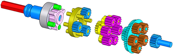
Most modern incarnations of this idea are arranged similar to planetary gearboxes. Here's one I built in 2018 -- please ignore the awful print quality; I was tweaking settings to try and get more accurate involute gear profiles.
S1 and S2 in my design are the two ring gears: They differ by one tooth, and the four planet gears have a step in their diameters so they mesh well with both rings. When the planets complete a full revolution about the central sun gear the rings move relative to each other by a single tooth. The central sun gear just keeps the planets in position, but I used it as an input because I didn't feel like building a frame to directly turn the planets.
I came up with this independently-ish. In hindsight I had read about the concept in Layton Hale's "Principles and techniques for designing precision machines" but I had forgotten that at the time, so I spent a few days going "I can't possibly have invented this, it's too useful and obvious. It must be flawed in some way other than the quality of my prints."
I was right, and the flaw is pretty simple: The teeth of my planet gears and White's crank roller both experience the high surface speeds of the system input and the high surface forces of the system output. As you increase the gear ratio in these systems the product of speed and force on those teeth increases quadratically. The product of speed and force is power, and several paragraphs ago I said real, imperfect gear teeth lose a certain fraction of their power as heat due to sliding friction. So, the friction losses in these systems increase quadratically with their gear ratio and that puts a practical limit on the reduction ratios they can offer in situations where power matters. They're very useful in certain situations, like if you just want high reduction to increase resolution, or if you want a lot of torque and a lot of resistance to backdriving but you're OK with low speeds like in aircraft landing gear mechanisms, but they're not very useful for robotics.
They also have so-so backlash characteristics: Much better than a staged planetary system because there's just one set of teeth meshing, but much worse than a strain wave system because the gears aren't flexibly compressed into each other.
As an aside, my confusion about the novelty of my little gearbox lasted a few days because these things are wicked hard to google now. This sort of system used to be called an epicyclic gearbox, but that name has drifted to mean "any planetary gearbox." You might also refer to these as "differential" gearboxes because differential motion is used to produce the output, but that also means something very different in modern terms.
The last precursor I want to talk about before we get to the Archimedes Drive is the NIF differential friction drive:
This is the same concept but they used ball bearings as friction rollers instead of toothed gears. The goal of the project was to economically produce a couple thousand reduction drives for leadscrew actuators that would adjust the mirrors of the National Ignition Facility's laser systems at the nanometer scale.
The nice thing about this toothless system is it completely fixes the "losses grow quadratically with gear ratio" issue. Pure rolling motion is much, much lower drag than gear teeth meshing. The losses are still quadratic, but the constant factor for the coefficient of friction is several hundred times smaller so they just don't matter up to ridiculously high gear ratios.
The NIF drive was also superbly cheap to machine: Accurate steel balls are a commodity, and the bearing rings are simple axially symmetric shapes to turn on a lathe.
The bad thing about toothless systems, also known as friction drives, is they're completely unforgiving about tolerances. Normally your gear ratio is set by discrete numbers of teeth and unaffected by part tolerances, but if one of your race angles is off by a fraction of a degree in this system then your gear ratio will be slightly off as well. Worse, every rolling contact in this system is relying on friction, and friction only gives you traction if you give it normal force. The whole system has to be toleranced such that all these hard steel components are gently compressed against one another, but if you compress too much the contact points will exceed the yield strength of the steel and permanently dent. Actually, at about half the compression which would immediately cause dents the steel will begin to "fatigue," where tiny cracks grow a tiny bit each time it's compressed until eventually the part fails. These two limits box you in, and the tolerances of your parts force you to leave wide safety margins around both limits, so in the end friction drives can't handle much torque.
What Makes the Archimedes Drive Special
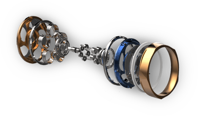
Jack's drive is the exception to that rule. The "Archimedes Drive" is arranged much like my junky little 3D print above, except it's toothless and the planets are hollow thin walled cylinders. The hollow planets act like springs: They're slightly squished, so they're a little bit elliptical instead of being perfectly round.
The springiness of the hollow planets frees IMSystems from the unforgiving tolerances of normal friction drives. A spring produces force as a constant multiple ("spring constant" k) of the distance it's been compressed from its uncompressed length. Springs with higher k values are stiffer, which means their force increases faster as they're compressed. In a sense the ball planets of the NIF drive are springs too, but they're solid steel balls so their k value is sky high. If you squeeze them a hundredth of a millimeter too much the force quadruples and something breaks. If you squeeze them a hundredth of a millimetertoo little the force falls to zero and they lose traction.
By making the planets hollow and adjusting the thickness of their walls, IMSystems can control the spring constant k and set it to the optimal value for their system. As I understand it, that optimal value is "as low as possible without exceeding the fatigue limits of our material." A lower spring constant widens the range of planet and ring diameters which create good normal force and therefore good torque, and lets them safely push closer to the material limits and increase their maximum torque. The Archimedes drive also benefits from using cylinders with line contact instead of balls with point contact in the NIF drive - max torque is more or less linear with respect to contact area, so this is a huge boost. It's the same as switching from ball bearings to roller bearings.
Now let's step away from all the Archimedes drive's interesting precursors and talk about the systems it's going to be replacing. It has zero backlash, higher power density than a harmonic drive, higher stiffness, it's more efficient which makes it highly backdriveable, it has a longer lifetime, and it's made from much simpler components. Please submit a correction on Github if I'm wrong here, but I don't see any niche where strain wave gearing wins once the Archimedes Drive is mature. There are some other interesting contenders like the AMBIDEX robot's cable drives or big pancake BLDC direct drive motors with new and improved control systems, but I think what IMSystems has built so far is an "existence proof" for the harmonic drive's complete replacement in the near future.
It's going to be wildly exciting to see where IMSystems' price point lands. If they knock a factor of 2-3 off Harmonic Drives that's pretty awesome for robotics, if it's a factor of 10 we're in "throw awesome little quadruped bots at every problem territory."
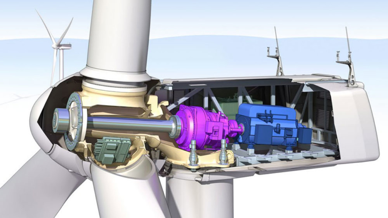
The other great thing about the Archimedes drive's high efficiency is that it works in reverse as a speed multiplier gearbox. Speed multiplying gearboxes are important for converting slow, powerful rotations like a wind turbine into the fast, lower torque input an electric generator wants to run on, and their reliability and power density is a fairly important factor limiting those systems today.
Lastly, that ability to "run in reverse" has major robotics implications as well: Electric motor control electronics can sense how much torque the motor is outputting, and that signal can be used to more precisely control robotic systems. With a gearbox of middling efficiency a gentle torque on the output will be completely stopped by gearbox friction and the motor won't see anything change, but with a high efficiency one like the Archimedes Drive even minute forces on the output will be transmitted back where the motor can sense it. The next generation of robots will need to safely interact with humans, and this is an important step in that direction. A system that can sense outside forces can stop when it hits something unanticipated like an errant human body part, and it can interact gently with squishy, fragile bodies.
This is exactly the kind of technology I made this site section to talk about. It's a weird little corner of industrial technology, the market leader has 220 twitter followers, and yet the knock-on effects might dramatically change everyday life within a decade. Cheaper wind energy (which, surprisingly to me, is still a much larger component of renewable generation than solar!), ubiquitous high performance robots, torquier electric bikes, and more might be coming soon because this little company invented some brilliant tweaks on a 250 year old gearing concept. If you want to follow their development, Jack's twitter has awesome testing videos every so often.